Appearance
Y402-4411-L Wireless I/O Sync System Manual
Refer to the detailed specification for electrical ratings, pinouts, and installation requirements: Y402-4411-L Specification.
1. Overview
The Y402-4411-L is a one-to-many wireless I/O control system that uses LoRa technology for long-range signal transmission between one Master and multiple Slave devices.
How it works:
- Master -> Slave: When the Master's input is activated, all 4 relay outputs on every Slave respond simultaneously.
- Slave -> Master: When any input on any Slave is activated, the Master's relay output responds.
- The Master output resets only after all Slave inputs return to open.
This architecture is designed for single-point trigger and multi-point response applications.
2. Basic Setup
Your system includes a Master device (1DI/1DO) and one or more Slave devices (4DI/4DO).
Follow these steps to get your system running:
| Step | Action | Details |
|---|---|---|
| 1 | Identify devices | Master size is 88 x 37 x 59 mm; Slave size is 88 x 72 x 59 mm. |
| 2 | Power up | Connect 9-36V DC power to all devices. |
| 3 | Check pairing | Factory-matched sets are already paired and ready to communicate. |
| 4 | Connect inputs | Wire dry-contact switches or NPN signals to DI terminals. |
| 5 | Connect outputs | Wire loads or contactors to relay output terminals (NO/COM/NC). |
| 6 | Install antennas | Mount antennas vertically in an open area, away from metal objects. |
3. Safety Notes
Important safety guidelines:
- Power supply: Use a certified DC power supply and observe correct polarity.
- Environment: Do not use in explosive, high-humidity, or dusty environments.
- Input type: Do not apply active voltage directly to DI terminals.
- Antenna: Use antennas in the 398-525 MHz range to ensure reliable communication.
4. Pairing Method
Devices purchased as a set are already paired at the factory and can communicate after power-up.
To add a new Slave to an existing system:
Step 1: Power the new Slave
Apply 9-36V DC power and verify the Power LED is on.
Step 2: Enter pairing mode
Press the pairing button on the Master, then press the pairing button on the new Slave.
Step 3: Wait for link confirmation
After successful pairing, the Link indicators remain on steadily.
Troubleshooting: If pairing fails, move the devices closer, verify antenna connection and power wiring, then repeat the pairing process.
Step 4: Complete
The new Slave is now part of the system and will follow the Master-to-Slave and Slave-to-Master logic automatically.
5. Wiring Instructions
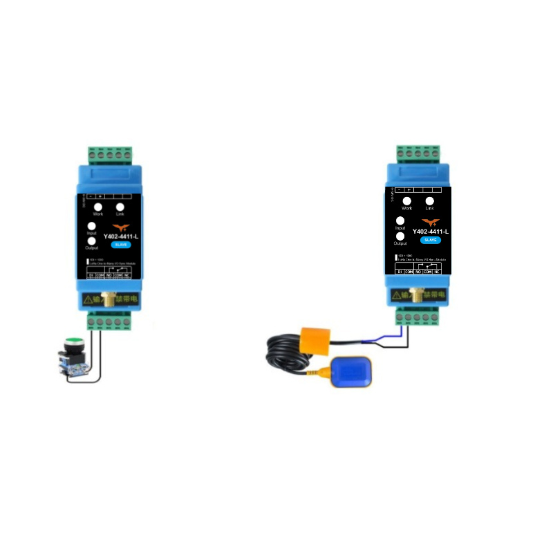
5.1 Input Connection (Switch/Sensor Side)
The Y402-4411-L input terminals support dry contact and NPN signal input.
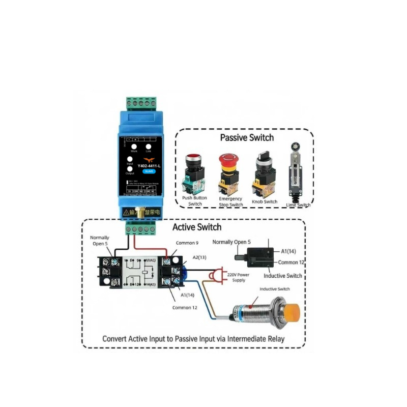
Method A: Mechanical Switches (Recommended)
Use this method for push buttons, selector switches, float switches, and relay contacts.
Direct connection: Wire the switch between DI and COM. No external power is needed on the input side.
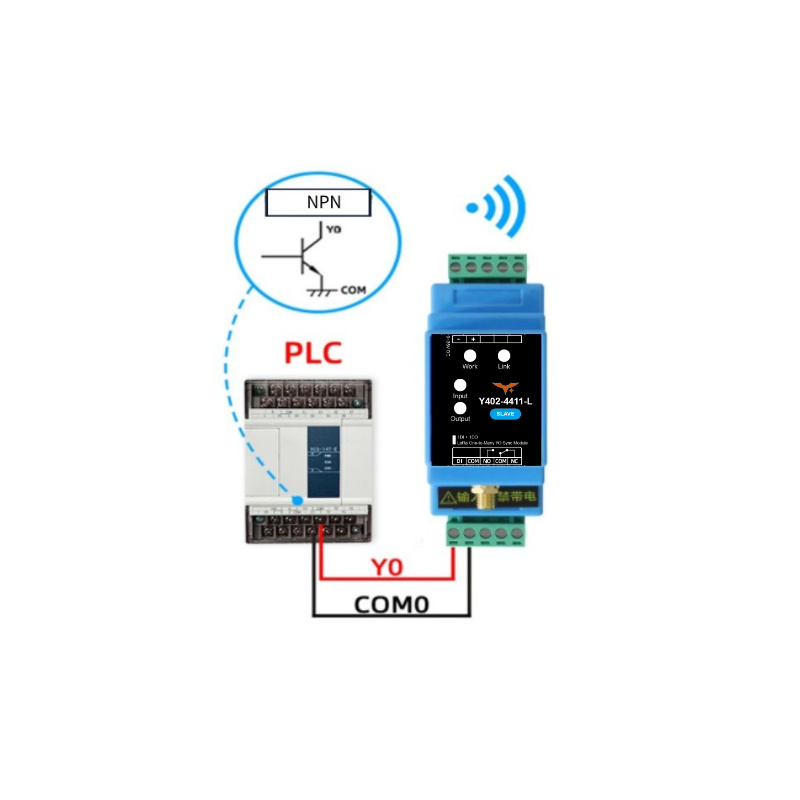
Method B: NPN Sensors
Use this method for NPN-type sensors such as proximity sensors and photoelectric sensors.
Wiring: Connect sensor emitter to COM and collector to DI.
Method C: Active/Powered Signals (PLC, Controller Outputs)
Active voltage outputs must be converted before entering DI terminals.
Use an intermediate relay: Convert the powered signal to a dry contact, then wire relay contacts to DI and COM.
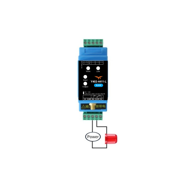
5.2 Output Connection (Load Side)
Choose the output wiring method based on load power:
Small Loads (<= 1 kW)
For resistive loads up to 1 kW, connect the load directly through relay contacts.
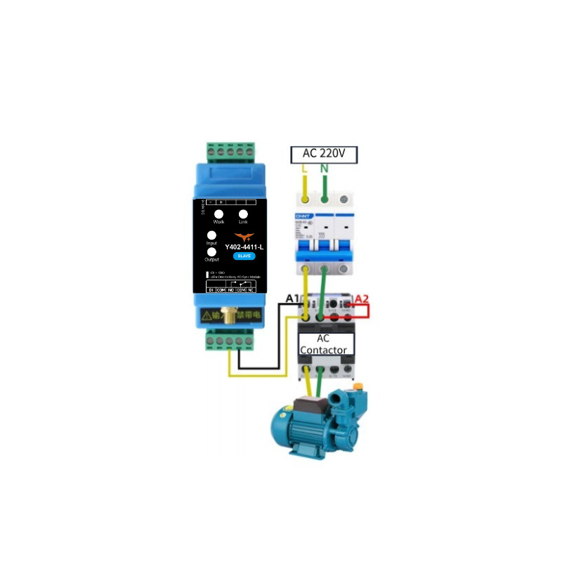
Large Loads (> 1 kW)
For high-power loads, use relay output to drive an AC contactor or external power relay.
Example: Use relay output as contactor coil control for motors or large heating equipment.
6. Important Usage Notes
Real-time Considerations
The Y402-4411-L uses half-duplex wireless communication. Transmission delay varies with distance and environment. Do not use this product for hard real-time safety control, such as emergency stop loops.
Topology and Channel Mapping
- Only one Master is allowed in a system.
- One Master can manage multiple Slaves.
- Mapping logic:
- Master channel 1 input -> Slave channels 1 to 4 outputs
- Any Slave channel 1 to 4 input -> Master channel 1 output
Antenna Installation
| Parameter | Requirement |
|---|---|
| Frequency | 398-525 MHz |
| Mounting | Vertical orientation |
| Height | About 2 meters above ground |
| Clearance | Keep away from large metal objects |
| Connection | Ensure SMA connector is fully tightened |
Tip: Good antenna placement significantly improves link stability and communication range.
- Manufacturer: Hunan YenGear Tech Co., Ltd.
- Address: Room 21014, Building 1, Fudi Xingguang Tiandi, Yingxin Road, Yuhua District, Changsha, Hunan, China
- Email: [email protected]
- Website: www.yengear.com