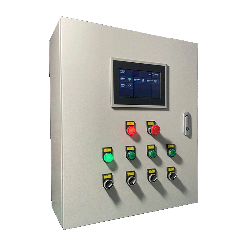
Appearance
Y951 Smart Distribution Box Specification
Contents
- Overview
- Ordering Information
- Key Features
- Selection Guide
- Technical Specifications
- Function and Operation
- Installation
- Important Notes
1. Overview
The Y951 is a series of smart distribution boxes designed for centralized power supply and remote control across multiple circuits. Supporting 2 to 16 circuits, the series offers various communication options: -G for 4G, -W for WiFi, and -R for RJ45 Ethernet. For example, the Y951-4-G is a 4-circuit 4G smart distribution box.
Built on an industrial-grade architecture, the Y951 integrates remote control, scheduled tasks, status monitoring, and electrical protection. It is ideal for aquaculture, livestock farming, greenhouses, pump/valve control, and environmental monitoring.
Users can remotely monitor device status and control individual circuits via the platform or mobile app. Optional features include current monitoring, power failure/phase loss detection, audible/visual alarms, and integrated displays.
Operating Principle
- The box connects to a
220V/380V ACpower source to provide centralized distribution. - An internal smart control unit communicates with the platform via
4G,WiFi, orEthernet. - Users issue start/stop, timing, or linkage commands through the cloud platform.
- Each circuit operates independently and provides real-time status feedback.
- The system supports local automatic linkage, remote manual control, and cloud-based automation.
Application Scenarios
- Centralized power supply for pumps, fans, aerators, and lighting.
- Automated management of agricultural and greenhouse environmental equipment.
- Unattended power distribution for construction sites and remote stations.
- Unified operation and maintenance (O&M) for distributed power facilities.
2. Ordering Information
2.1 Model Naming
text
Y951-xx-C
  │   │  └── C: Communication (G / W / R)
  │   └───── xx: Number of circuits (2~16)
  └───────── Y951: Smart Distribution Box Series
2.2 Communication Suffix
| Suffix | Communication | Description |
|---|---|---|
-G | 4G | Best for remote sites without wired internet |
-W | WiFi | Best for areas with existing wireless network coverage |
-R | RJ45 Ethernet | Best for stable wired environments like server rooms |
2.3 Typical Models
| Model | Circuits | Description |
|---|---|---|
| Y951-2-G | 2 | 2-circuit 4G smart distribution box |
| Y951-4-G | 4 | 4-circuit 4G smart distribution box |
| Y951-4-W | 4 | 4-circuit WiFi smart distribution box |
| Y951-8-R | 8 | 8-circuit Ethernet smart distribution box |
| Y951-12-G | 12 | 12-circuit 4G smart distribution box |
| Y951-16-R | 16 | 16-circuit Ethernet smart distribution box |
2.4 Selection Checklist
| Item | Recommendation |
|---|---|
| Model | Y951-xx-C, confirm circuit count and communication |
| Input Voltage | 220V AC or 380V AC |
| Load per Circuit | Standard 2.2 kW; customization available for higher loads |
| Communication | 4G, WiFi, or RJ45 Ethernet |
| Enclosure Material | Galvanized steel or Stainless steel |
| Dimensions | Standard or project-specific sizes |
| Mounting | Wall-mounted or Pole-mounted |
| Extensions | Current monitoring, phase loss detection, GPS, etc. |
| Control Logic | Remote start-stop / Timing / Linkage / Reversing control |
2.5 Package Contents
| Quantity | Item |
|---|---|
| 1 | Y951 Smart Distribution Box |
| 1 | Product Documentation |
| 1 | Warranty Information |
Optional Accessories: 7-inch display, current monitoring module, phase loss module, audible/visual alarm, GPS module.
3. Key Features
- Flexible Circuit Count —
2to16circuits to suit different project scales. - 2.2 kW Standard Load — Ideal for pumps, fans, and lighting; supports higher load customization.
- Versatile Communication — Supports
4G,WiFi, andRJ45 Ethernetfor diverse site conditions. - Multi-Mode Control — Supports manual, remote, scheduled, and cloud-linked control.
- Modular Design — Organized internal wiring for easy installation and maintenance.
- Robust Protection — Features overload, short-circuit, and high-voltage protection; uses
12~24V DCsafe control voltage. - Expandable Monitoring — Optional current, power failure, and phase loss monitoring.
- Cloud Visualization — Uploads usage data and logs for graphical analysis and O&M tracking.
- Custom Enclosures — Durable galvanized or stainless steel boxes tailored to the environment.
4. Selection Guide
4.1 Model Comparison
| Model | Circuits | Comm. | Std. Load | Dimensions (Ref.) | Typical Use Case |
|---|---|---|---|---|---|
| Y951-2-G | 2 | 4G | 2.2 kW | 500 × 600 × 200 mm | Small pumps, lighting |
| Y951-4-W | 4 | WiFi | 2.2 kW | 400 × 500 × 200 mm | WiFi-covered facilities |
| Y951-6-G | 6 | 4G | 2.2 kW | 500 × 600 × 200 mm | Medium-scale fan/pump control |
| Y951-8-R | 8 | RJ45 | 2.2 kW | 600 × 800 × 200 mm | Server rooms, industrial zones |
| Y951-12-G | 12 | 4G | 2.2 kW | Custom | Large-scale centralized control |
| Y951-16-R | 16 | RJ45 | 2.2 kW | 1500 × 700 × 370 mm | Complex facility distribution |
4.2 Quick Selection Tips
- For 2–4 circuits in tight spaces, choose the
Y951-2-*orY951-4-*series. - Use -G (4G) for remote sites or areas without wired internet.
- Use -W (WiFi) for indoor sites with stable wireless LAN.
- Use -R (Ethernet) for server rooms or industrial networks.
- If the load exceeds
2.2 kWor you require specific monitoring/display features, contact us for customization.
5. Technical Specifications
5.1 Electrical Parameters
| Parameter | Specification |
|---|---|
| Input Voltage | 220V / 380V AC |
| Circuits | 2 to 16 |
| Load per Circuit | 2.2 kW (Standard) |
| Max Load | Customizable |
| Control Voltage | 12~24V DC |
| Total Current | 20A (Standard; Customizable) |
5.2 Communication and Data
| Parameter | Specification |
|---|---|
| Communication | 4G / WiFi / RJ45 Ethernet |
| Model Suffix | -G / -W / -R |
| Data Transfer | Wired or wireless network |
| Upload Interval | Default: 1h (Adjustable) |
| Remote Access | Platform / Mobile App / WeChat Mini Program |
| Control Modes | Remote Start/Stop, Scheduling, Linkage |
5.3 Protection Indicators
| Parameter | Specification |
|---|---|
| Under-voltage | 170V ±5% (Optional) |
| Over-voltage | 270V ±5% (Optional) |
| Action Time | ≤100 ms |
| Detection Time | ≤100 ms |
| Short-circuit | ≤6000 A |
| Fault Notification | App alert; optional audible/visual alarm |
| Self-test | Closed-loop control with individual circuit self-testing |
5.4 Environmental and Mechanical
| Parameter | Specification |
|---|---|
| Operating Temp | -40°C to 85°C |
| Color | Gray / Off-white (Variant dependent) |
| Material | Galvanized steel (Default) / Stainless steel (Optional) |
| Dimensions | Dependent on circuit count and configuration |
| Mounting | Wall-mounted / Pole-mounted |
6. Function and Operation
6.1 Core Functions
| Function | Description |
|---|---|
| Remote Control | Start or stop individual circuits remotely |
| Scheduling | Automatically switch circuits based on set time plans |
| Cloud Linkage | Trigger actions based on external sensor data |
| Logs | View real-time status and historical operation records |
| Security Alerts | Push notifications for threshold violations or faults |
6.2 Operation Logic
- Power on the device and connect to the network. Check online status on the platform.
- Issue commands (on/off/timer) for specific circuits via the app.
- Set thresholds for sensors to trigger automatic equipment operation.
- If protection is enabled, the system automatically cuts power during overload, short-circuit, or voltage anomalies and reports the status.
6.3 Controls and Indicators
- Emergency Stop — Quickly cuts control power during emergencies.
- Run Indicator — Lights up when the circuit is active.
- 3-Position Switch — Manual On / Manual Off / Auto Control.
- 4-Position Reversing Switch — For motors; supports Stop / Reverse / Forward / Auto.
7. Installation
7.1 Mounting Methods
- Wall Mounting — Secure to the wall using expansion bolts.
- Pole Mounting — Suitable for outdoor or field installations with pole supports.
7.2 Installation Tips
- Install in a ventilated area that is easy to observe and maintain.
- For outdoor use, ensure secure mounting and use waterproof cable glands for entry/exit points.
- Keep wireless antennas away from metal enclosures and high-current cables to avoid interference.
- Verify circuit loads, phase sequence, and protection settings before powering on.
- Do not modify internal wiring; contact professional personnel for adjustments.
8. Important Notes
- Model ID —
xxdenotes circuits,Cdenotes communication. Supports2–16circuits. - Load Limit — Standard load is
2.2 kWper circuit. Confirm customization for higher loads. - Comm. Variants —
-Gis 4G,-Wis WiFi,-Ris RJ45 Ethernet. - Customization — Enclosure size, material, color, and components are customizable.
- Electrical Safety — Installation and maintenance must be performed by qualified professionals.
- Maintenance — Periodically inspect wiring, contactors, and breakers; keep the box free of dust.
- Optional Features — Current monitoring, GPS, and displays must be specified during ordering.
- Manufacturer: Hunan YenGear Tech Co., Ltd.
- Address: Room 21014, Building 1, Fudi Xingguang Tiandi, Yingxin Road, Yuhua District, Changsha, Hunan, China
- Email: [email protected]
- Website: www.yengear.com