Appearance
Y403-11-L Wireless I/O Sync System Manual
Refer to the detailed specification for electrical ratings, pinouts, and installation requirements: Y403-11-L Specification.
1. Overview
The Y403-11-L is a wireless switch controller that uses LoRa wireless technology to transmit switch signals between devices.
How it works: When you press a switch connected to one device, the signal travels wirelessly to another device, turning its relay output on or off. Multiple devices can relay signals through each other, extending the communication range even in environments with obstacles like walls or buildings.
2. Basic Setup
Follow these steps to get your system running:
| Step | Action | Details |
|---|---|---|
| 1 | Power up | Connect DC power to all devices. See specification for voltage range. |
| 2 | Check pairing | Factory-matched units are already paired and ready to communicate. |
| 3 | Connect inputs | Wire switches or sensors to the input terminals (dry contact only). |
| 4 | Connect outputs | Wire your load or contactor to the relay output terminals (NO/COM/NC). |
| 5 | Install antennas | Mount antennas vertically in an open area, away from metal objects. |
3. Safety Notes
⚠️ Important safety guidelines:
- Power supply: Use a certified power supply and observe correct polarity when connecting.
- Environment: Do not use in explosive, high-humidity, or dusty environments.
- Antenna: Use only antennas within the specified frequency range (398–525 MHz) to ensure reliable communication.
4. Pairing Method
Devices purchased together are already paired at the factory and will communicate immediately when powered on.
To add a new device to an existing system:
Step 1: Wire the devices
Connect 2 power lines and 3 communication lines between the new device and any existing device in your system.
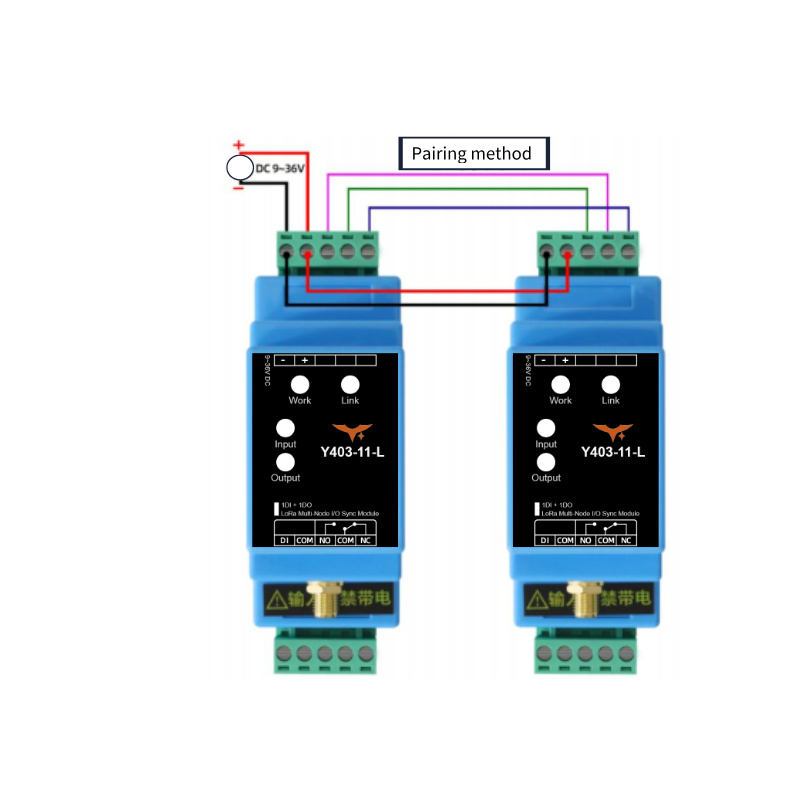
Step 2: Power on
Apply 9–36V DC power to both devices. The power indicators on both devices should light up steadily.
Step 3: Wait for pairing
Within approximately 30 seconds, the connection indicators on both devices will light up steadily, indicating successful pairing.
Troubleshooting: If the connection indicators do not light up after 30 seconds, power off both devices, check all wiring connections, and power on again.
Step 4: Complete
Disconnect the communication lines. The new device is now part of your system and can communicate with all other paired devices.
5. Wiring Instructions
5.1 Input Connection (Switch/Sensor Side)
The Y403-11-L input terminals accept dry contact signals only (no voltage present). Choose the appropriate wiring method based on your signal type:
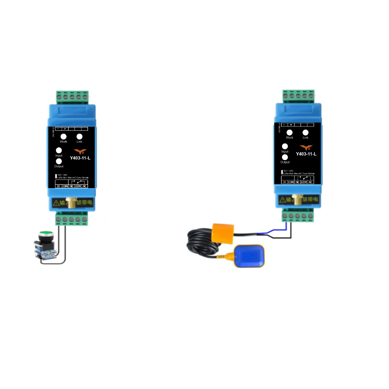
Method A: Mechanical Switches (Recommended)
Use this method for simple mechanical switches like push buttons, toggle switches, float switches, or relay contacts.
✓ Direct connection: Wire the switch between the input terminal and common terminal. No external power needed.
Method B: NPN Sensors
Use this method for NPN-type proximity sensors or photocells.
✓ Wiring: Connect sensor emitter to COM terminal, sensor collector to input terminal. Important: Do not connect these sensors to any external power source—they are powered internally by the Y403-11-L.
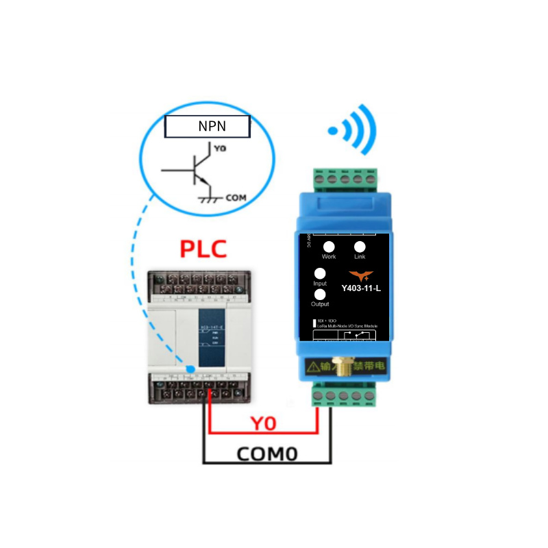
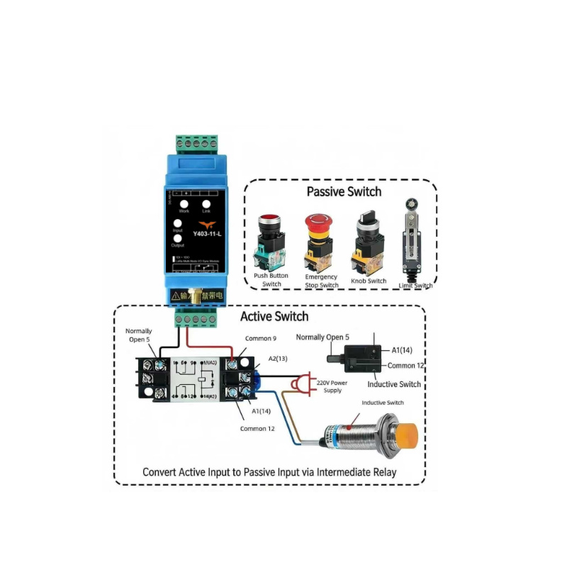
Method C: Active/Powered Signals (PLC, Controller Outputs)
Use this method when connecting to PLC outputs or other powered control signals.
⚠️ Must convert first: Active signals cannot connect directly. Use an intermediate relay to convert the powered signal to a dry contact, then connect the relay contacts to the input terminals.
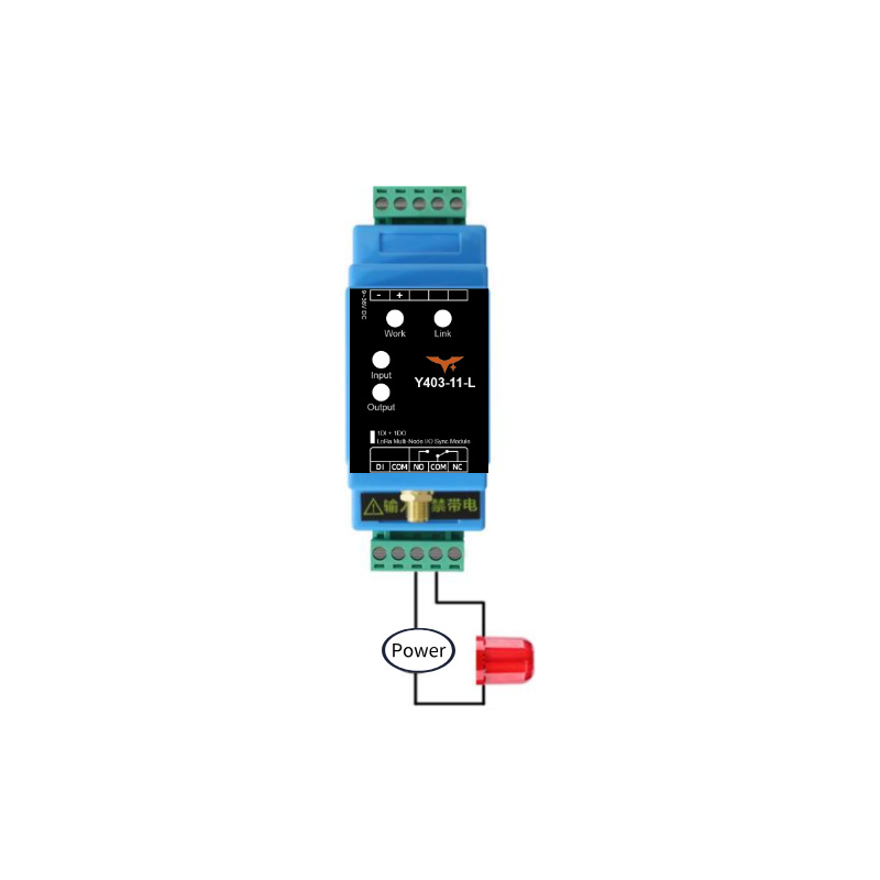
5.2 Output Connection (Load Side)
Choose the appropriate wiring method based on your load power requirements:
Small Loads (≤ 1 kW)
For resistive loads up to 1 kW (lights, small heaters), connect directly to the relay output.
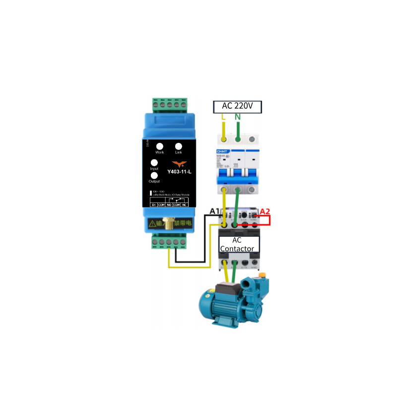
Large Loads (> 1 kW)
For high-power devices, use the Y403-11-L to control a contactor, which then switches the heavy load.
Example: Controlling a 3-phase motor or large heating element with a 220V AC contactor.
6. Important Usage Notes
Real-time Considerations
The Y403-11-L uses half-duplex wireless communication. Signal transmission time varies based on environmental conditions and distance. Not suitable for applications requiring precise real-time control, such as emergency stop circuits or high-speed machinery synchronization.
Antenna Installation
| Parameter | Requirement |
|---|---|
| Frequency | 398–525 MHz only |
| Mounting | Vertical orientation |
| Height | Approximately 2 meters above ground |
| Clearance | Keep away from large metal objects and structures |
| Connection | Ensure antenna connector is tightly screwed |
Tip: Proper antenna placement significantly improves communication range and reliability.
- Manufacturer: Hunan YenGear Tech Co.,Ltd
- Address: Room 21014, Unit 1, Fudixingguang plaza, Yuhua district Yingxin road, Changsha, Hunan, P.R. China
- Email: [email protected]
- Website: www.yengear.com