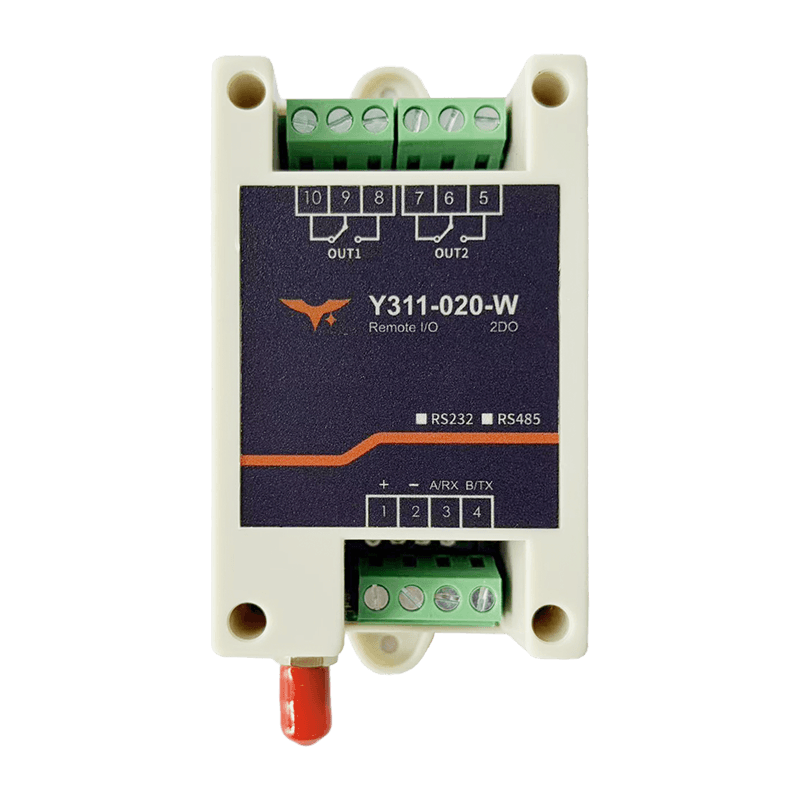
Appearance
Y311-020-W/R Remote I/O Module Specification
| Y311-020-W | Y311-020-R |
|---|---|
 |  |
Reference: Y311-010/020-W/R Technical Manual
Contents
- Overview
- Ordering Information
- Key Features
- Technical Specifications
- Interfaces and Indicators
- Mechanical and Environmental
- Installation and Wiring
- Important Notes
1. Overview
Y311-020 is available in two network variants:
Y311-020-W: Wi-Fi versionY311-020-R: RJ45 Ethernet version
Both models are dual-channel remote relay control modules with 2 x 10 A independent outputs. They are well suited for dual-light control, pump and valve switching, remote reset, and simple interlock scenarios. The main difference is the network interface and default network settings.
| Model | DI | DO | Connectivity | Typical Applications |
|---|---|---|---|---|
| Y311-020-W | 0 | 2 x 10 A relay | 2.4 GHz Wi-Fi, AP/STA | Dual-light control, pumps, valves, alarm beacons, remote reset |
| Y311-020-R | 0 | 2 x 10 A relay | 10/100M RJ45 Ethernet | Dual-light control, pumps, valves, alarm beacons, remote reset |
2. Ordering Information
2.1 Model Naming
text
Y311 - 0 2 0 - W / R
  |        | \------ W: Wi-Fi; R: RJ45 Ethernet
  |        \-------- 020: 0 x DI / 2 x DO / 0 x AI
  \----------------- Y311: Remote I/O module family
2.2 SKU and Network Capability
| SKU | Description | Connectivity | Interfaces | Power |
|---|---|---|---|---|
| Y311-020-W | 0DI + 2DO, Wi-Fi remote relay module | 2.4 GHz Wi-Fi AP/STA | Power terminal, Wi-Fi antenna, dual relay terminals, RESET | 7 to 40 VDC |
| Y311-020-R | 0DI + 2DO, Ethernet remote relay module | 10/100M RJ45, static IP or DHCP | Power terminal, RJ45, dual relay terminals, RESET | 7 to 40 VDC |
2.3 Standard Package
- Y311-020-W or Y311-020-R main unit x1
- Pluggable terminal x1
- Quick-start card x1
- Warranty card x1
3. Key Features
- Dual
10 ARelay Outputs: Control two independent loads from one compact module. - Wi-Fi or Ethernet Options: Select
-Wfor wireless access or-Rfor fixed wired deployment. - Wide
7 to 40 VDCInput: Works with common industrial power systems. - Pulse and Timed Switching: Supports flash-on, flash-off, full-on or full-off, and timed actions.
- Modbus TCP Integration: Standard register access fits cloud platforms, SCADA, and common Modbus tools.
- Compact Control Hardware: Built for edge cabinets, small distribution boxes, and endpoint control panels.
4. Technical Specifications
4.1 Network and Communication
| Parameter | Y311-020-W | Y311-020-R |
|---|---|---|
| Network Interface | 2.4 GHz Wi-Fi | 1 x RJ45, 10/100 Mbps |
| Network Mode | AP / STA | Static IP / DHCP |
| Default Management IP | 192.168.16.254 | 192.168.1.7 |
| Default Port | 60000 (AP) / 10000 (TCP) | 10000 |
| Protocol | Modbus, TCP Server | Modbus, TCP Server |
| Baud Rate | 2400 / 4800 / 9600 / 19200 / 38400 bps | 2400 / 4800 / 9600 / 19200 / 38400 bps |
| Device Address | 0 to 255, broadcast 0xFE supported | 0 to 255, broadcast 0xFE supported |
4.2 Digital Output
| Item | Specification |
|---|---|
| Channel Count | 2 x relay |
| Contact Rating | 10 A @ 30 VDC / 10 A @ 250 VAC |
| Response Time | Operate <10 ms, release <5 ms |
| Control Modes | Manual, flash-on, flash-off, all-on or all-off, timed |
4.3 Electrical and System
| Parameter | Specification |
|---|---|
| Supply Voltage | 7 to 40 VDC |
| Power Consumption | Standby < 2.5 W; both relays energized < 5 W |
| Indicators | PWR, DO1, DO2 |
| Reset | Long press to restore default network settings |
5. Interfaces and Indicators
5.1 Interface Definition
| Interface | Y311-020-W | Y311-020-R |
|---|---|---|
V+ / V- | 7 to 40 VDC power input | 7 to 40 VDC power input |
| Wi-Fi Antenna | Standard | Not available |
| RJ45 | Not available | Standard |
COM / NO (DO1) | Standard | Standard |
COM / NO (DO2) | Standard | Standard |
RESET | Standard | Standard |
5.2 LED Indicators
| LED | Status | Description |
|---|---|---|
PWR | Solid on / blinking | Solid on = powered; blinking = communication activity |
DO1 | Solid on | Relay 1 energized |
DO2 | Solid on | Relay 2 energized |
6. Mechanical and Environmental
| Parameter | Specification |
|---|---|
| Dimensions | 97 x 50 x 32 mm |
| Weight | About 185 g |
| Housing | Flame-retardant ABS, IP20 |
| Operating Temperature | -40 to 85 C |
| Humidity | 5 to 95% RH, non-condensing |
7. Installation and Wiring
- Connect a
7 to 40 VDCpower supply and confirm thePWRindicator is normal. - For
-W, connect the device to Wi-Fi. For-R, connect the RJ45 Ethernet cable. - Wire the two relay channels according to the load circuits.
- Set the device address and network parameters, then verify switching with Modbus commands.
8. Important Notes
Y311-020-WandY311-020-Rare two separate models, not one device with both Wi-Fi and RJ45.- If digital inputs are required, choose the
Y311-440/660/880family. - For inductive loads, add an RC snubber, TVS device, or flyback diode.
- Change the default network settings and access password before deployment.
- Manufacturer: Hunan YenGear Tech Co., Ltd.
- Address: Room 21014, Building 1, Fudi Xingguang Tiandi, Yingxin Road, Yuhua District, Changsha, Hunan, China
- Email: [email protected]
- Website: www.yengear.com