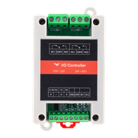
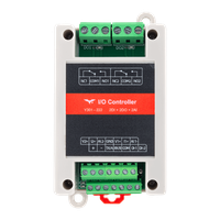
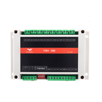
Appearance
Y301 ControlLink Series User Manual
Applicable models: Y301-220, Y301-222, Y301-440, Y301-444, Y301-880.
- Y301-220/222 Specification | Technical Manual
- Y301-440/444 Specification | Technical Manual
- Y301-880 Specification | Technical Manual
Product Overview
ControlLink Series are I/O modules with digital inputs (DI), relay outputs (DO), and optional analog inputs (AI). They connect via RS485 using Modbus-RTU, suitable for pump, fan, valve, lighting, and sensor applications.
Key features:
- Integrated DI and DO on all models
- RS485 standard; RS232 and TTL available on selected models
- DC 5~36V power supply
- Dry and wet contact DI support
- Relay outputs for valves, lights, alarms, and contactors
- AI for 0~10V, 0~5V, or 4~20mA sensors (Y301-222 and Y301-444)
- DIN-rail or screw mounting
Model Selection
| Product | Model | DI | DO | AI | Recommended Use | |
|---|---|---|---|---|---|---|
 | Y301-220 | 2 | 2 | 0 | Small-scale control and monitoring | More Details |
 | Y301-222 | 2 | 2 | 2 | Mixed switch, relay, and sensor applications | More Details |
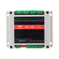 | Y301-440 | 4 | 4 | 0 | Multi-channel digital acquisition and control | More Details |
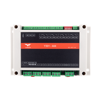 | Y301-444 | 4 | 4 | 4 | Combined digital and analog acquisition | More Details |
 | Y301-880 | 8 | 8 | 0 | High-density digital acquisition and relay control | More Details |
Default Parameters
| Parameter | Default Value |
|---|---|
| Communication protocol | Modbus-RTU |
| Device address | 1 |
| Baud rate | 9600 bps |
| Data bits / Stop bits / Parity | 8 / 1 / None |
| Power supply | DC 5~36V |
Note: Each RS485 device must have a unique address. Changes to address or baud rate require a restart. If communication fails, verify address, baud rate, A/B polarity, and GND connection.
Hardware Interfaces (Y301-444 Example)
The following uses Y301-444 (4 DI, 4 DO, 4 AI) as an example.
| Interface Area | Terminal | Description |
|---|---|---|
| Power | V+, V- | DC 5~36V |
| Communication | A, B, GND | RS485 terminals |
| DI Input | DI1~DI4, DICOM | Digital input for switches and contacts |
| DO Output | COMn, NOn, NCn | Relay output; n = channel number |
| AI Input | A1~A4, GND | Analog input (Y301-222 / Y301-444 only) |
| DIP Switch | SW1~SW5 | Address offset; see technical manual |
| Reload Button | Reload / Reset | Restore defaults or restart |
DO terminal definitions:
COM: CommonNO: Normally open (closes when relay on)NC: Normally closed (opens when relay on)
Wiring precautions:
- Power off before wiring
- Use shielded twisted pair for RS485; add 120Ω termination at both ends of long runs
- Add flyback diodes, RC snubbers, or surge protection for inductive loads
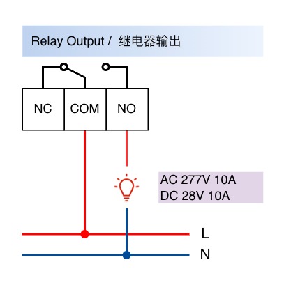
- Relay rating: AC 277V / 10A or DC 28V / 10A
DI Wiring Diagram
DI channels collect signals from switches, sensors, and contacts.
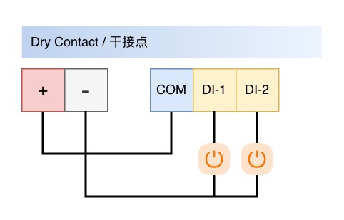
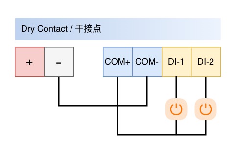
Dry Contact Input
 |  |
|---|
Wet Contact Input
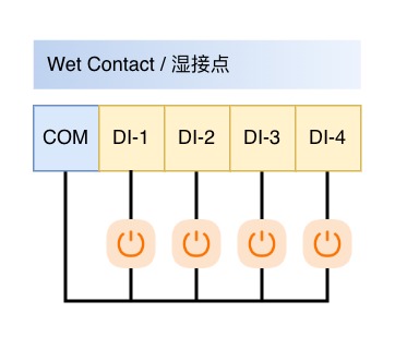
Wiring notes:
- Dry contact: connect switch between DI and common terminal
- Wet contact: connect DC 5~36V signal to DI and common reference to DICOM / GND
- DI channels collect signals only; they do not power external devices
DO Wiring Diagram
DO channels provide relay contact outputs for valves, lights, alarms, and contactors.
Standard Load
| High-Power Load | Three-Phase Load |
|---|---|
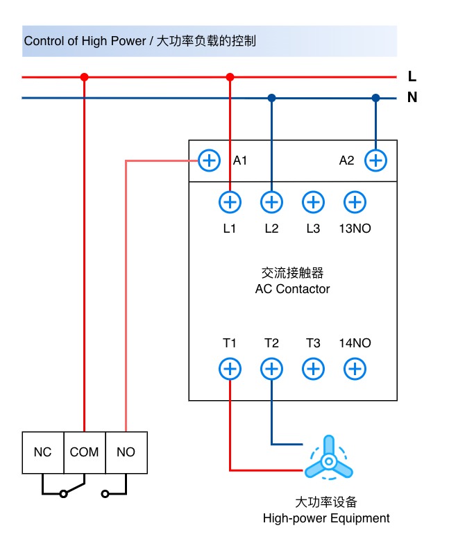 | 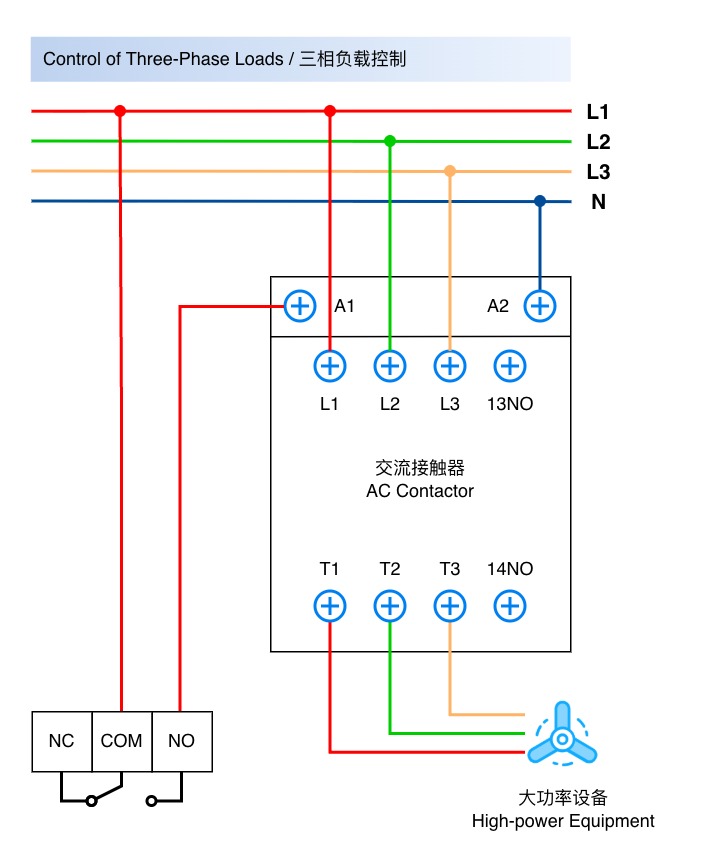 |
Wiring notes:
- Relay contacts do not output voltage; external load power is required
- Standard wiring: route load power line through COM and NO
- Use COM and NC for normally-on applications
- For AC high-voltage loads, use qualified personnel and proper insulation / fuses
AI Wiring Diagram
AI channels are available on Y301-222 and Y301-444 only.
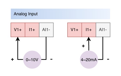
TIPS
Each AI channel supports either 0~10V or 4~20mA (default), not both. Request voltage mode when ordering if required.
Wiring notes:
- Two-wire 4~20mA sensors: connect in series following the sensor datasheet
- Three-wire sensors: connect SIG to AI and GND to module GND
- Four-wire sensors: connect signal output to AI and signal ground to GND
- Do not connect both voltage and current to the same AI channel
- Sensor range and AI mode must match
Common Applications
| Application | Recommended Model | Description |
|---|---|---|
| Two-channel status acquisition and two-channel relay control | Y301-220 | Small equipment control |
| Level, pressure, or temperature sensors with relay control | Y301-222 / Y301-444 | Process monitoring and automation |
| Multi-zone lighting, valve, or pump control | Y301-440 / Y301-880 | Control panels with multiple points |
- Manufacturer: Hunan YenGear Tech Co., Ltd.
- Email: [email protected]
- Website: www.yengear.com