
Appearance
Y301-440/444 Serial I/O Modules Technical Manual
| Y301-440 | Y301-444 |
|---|---|
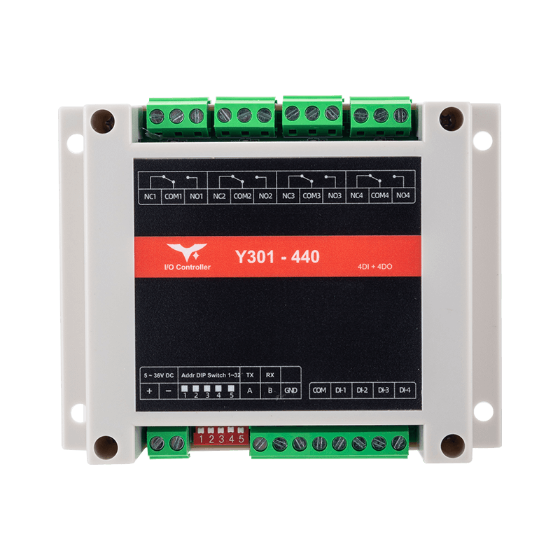 | 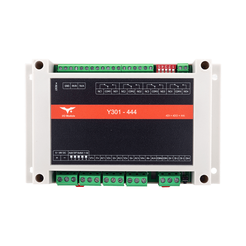 |
Contents
- Overview
- Default Settings
- Modbus Register Map (Modbus Address Only)
- Command Examples (CRC Included)
- Parameter Configuration
- Automation Rules
- Troubleshooting
1. Overview
This manual describes the Modbus RTU communication commands for the Y301-440 and Y301-444 I/O modules.
| Model | DI | DO | AI | Description |
|---|---|---|---|---|
| Y301-440 | 4 | 4 | 0 | Four inputs + four relays |
| Y301-444 | 4 | 4 | 4 | Four inputs + four relays + four analog inputs |
Frame format: [slave address][function code][data][CRC low][CRC high]
The examples below use slave address 0x01. Replace it with the actual device address and recalculate the CRC.
2. Default Settings
| Parameter | Default |
|---|---|
| Slave address | 1 |
| Baud rate | 9600 bps |
| Data bits | 8 |
| Stop bits | 1 |
| Parity | None |
| Output state hold | Keep after soft reboot (0x0040 = 1) |
| Pulse counting edge | Rising edge (0x0041 = 1) |
| Pulse debounce | 50 ms (0x0042 = 50) |
3. Modbus Register Map (Modbus Address Only)
3.1 Digital Input (DI) - Function Code 0x02
| Channel | Modbus Address | R/W |
|---|---|---|
| DI1 | 0x0000 | RO |
| DI2 | 0x0001 | RO |
| DI3 | 0x0002 | RO |
| DI4 | 0x0003 | RO |
Return value: 0 = inactive, 1 = active.
3.2 Digital Output (DO) - Function Code 0x01/0x05/0x0F
| Channel | Modbus Address | R/W |
|---|---|---|
| DO1 | 0x0000 | RW |
| DO2 | 0x0001 | RW |
| DO3 | 0x0002 | RW |
| DO4 | 0x0003 | RW |
For function code 0x05, write 0x0000 to open the NO contact or 0xFF00 to close it. Function code 0x0F uses packed bits: 0 = open, 1 = closed.
3.3 Analog Input (AI) - Function Code 0x04 (Y301-444 only)
| Channel | Modbus Address | Description | Unit | R/W |
|---|---|---|---|---|
| AI1 voltage | 0x0000 | AI1 sampled voltage | mV | RO |
| AI1 current | 0x0001 | AI1 sampled current | uA | RO |
| AI2 voltage | 0x0002 | AI2 sampled voltage | mV | RO |
| AI2 current | 0x0003 | AI2 sampled current | uA | RO |
| AI3 voltage | 0x0004 | AI3 sampled voltage | mV | RO |
| AI3 current | 0x0005 | AI3 sampled current | uA | RO |
| AI4 voltage | 0x0006 | AI4 sampled voltage | mV | RO |
| AI4 current | 0x0007 | AI4 sampled current | uA | RO |
Each AI channel can be wired for either voltage or current. The other reading is invalid.
3.4 Common Holding Registers (Parameters) - Function Code 0x03/0x06/0x10
| Modbus Address | Parameter | Bytes | R/W | Range / Enum | Default |
|---|---|---|---|---|---|
0x002A | Runtime slave address | 2 | RO | 0-255 | - |
0x002B | DIP offset address | 2 | RO | 0-31 | 0 |
0x003E | Slave address | 2 | RW | 1-255 | 1 |
0x003F | Broadcast mode | 2 | RW | 0/1/2 | 0 |
0x0040 | Output state hold | 2 | RW | 0/1/2 | 1 |
0x0041 | Pulse count edge | 2 | RW | 0/1 | 1 |
0x0042 | Pulse debounce (ms) | 2 | RW | 5-255 | 50 |
0x0055 | RTC Unix time | 4 | RW | uint32 | - |
0x0057 | Baud rate | 4 | RW | 600-230400 | 9600 |
0x0059 | Data bits | 2 | RW | 8,9 | 8 |
0x005A | Stop bits | 2 | RW | 1,2 | 1 |
0x005B | Parity | 2 | RW | 0/1/2 | 0 |
4. Command Examples (CRC Included)
4.1 Read Digital Inputs
| Operation | Request (Hex) |
|---|---|
| Read DI1 | 01 02 00 00 00 01 B9 CA |
| Read DI2 | 01 02 00 01 00 01 E8 0A |
| Read DI3 | 01 02 00 02 00 01 18 0A |
| Read DI4 | 01 02 00 03 00 01 49 CA |
| Read DI1~DI4 in one shot | 01 02 00 00 00 04 79 C9 |
4.2 Read Digital Output Status
| Operation | Request (Hex) |
|---|---|
| Read DO1 | 01 01 00 00 00 01 FD CA |
| Read DO2 | 01 01 00 01 00 01 AC 0A |
| Read DO3 | 01 01 00 02 00 01 5C 0A |
| Read DO4 | 01 01 00 03 00 01 0D CA |
| Read DO1~DO4 in one shot | 01 01 00 00 00 04 3D C9 |
4.3 Control Digital Outputs
| Operation | Command |
|---|---|
| Open DO1 | 01 05 00 00 00 00 CD CA |
| Close DO1 | 01 05 00 00 FF 00 8C 3A |
| Open DO2 | 01 05 00 01 00 00 9C 0A |
| Close DO2 | 01 05 00 01 FF 00 DD FA |
| Open DO3 | 01 05 00 02 00 00 6C 0A |
| Close DO3 | 01 05 00 02 FF 00 2D FA |
| Open DO4 | 01 05 00 03 00 00 3D CA |
| Close DO4 | 01 05 00 03 FF 00 7C 3A |
4.4 Read Analog Inputs (Y301-444 only)
| Operation | Request (Hex) |
|---|---|
| Read AI1 voltage | 01 04 00 00 00 01 31 CA |
| Read AI1 current | 01 04 00 01 00 01 60 0A |
| Read AI2 voltage | 01 04 00 02 00 01 90 0A |
| Read AI2 current | 01 04 00 03 00 01 C1 CA |
| Read AI3 voltage | 01 04 00 04 00 01 70 0B |
| Read AI3 current | 01 04 00 05 00 01 21 CB |
| Read AI4 voltage | 01 04 00 06 00 01 D1 CB |
| Read AI4 current | 01 04 00 07 00 01 80 0B |
| Read AI1~AI4 all (8 regs) | 01 04 00 00 00 08 F1 CC |
4.5 Parameter Read/Write
| Operation | Request |
|---|---|
Read slave address (0x003E) | 01 03 00 3E 00 01 E5 C6 |
| Write slave address = 5 | 01 06 00 3E 00 05 28 05 |
Read baud rate (0x0057, 2 regs) | 01 03 00 57 00 02 75 DB |
Write baud rate = 115200 (0x0001C200) | 01 10 00 57 00 02 04 00 01 C2 00 B7 D5 |
Write 8N1 (0x0059~0x005B) | 01 10 00 59 00 03 06 00 08 00 01 00 00 85 EF |
4.6 Special Operations
| Operation | Request |
|---|---|
Reboot (0x0800=0x5500) | 01 06 08 00 55 00 B4 FA |
Factory reset + reboot (0x0800=0x0055) | 01 06 08 00 00 55 4B 95 |
5. Parameter Configuration
5.1 Runtime Slave Address
Runtime slave address = configured address (0x003E) + DIP offset (0x002B).
5.2 Serial Settings
- Baud rate is a 32-bit value at
0x0057, use0x10to write 2 registers. - Data/stop/parity are located at
0x0059~0x005B. - Changing serial parameters or slave address requires reboot.
6. Automation Rules
The Y301-440/444 support DI -> DO automation, and the Y301-444 also supports AI threshold triggering. Up to 8 rules are supported, with 2 rules per DO.
6.1 Automation Register Map
Rules start at address 0x0080. Each rule uses 8 registers (16 bytes).
| Offset | Field | Description |
|---|---|---|
+0 | Mode | Rule type (see table below) |
+1 | Action | Mode-specific; see the mode table |
+2 | DO index | Target relay, starting from 1 |
+3 | Trigger index | Source DI or AI, starting from 1 |
+4-5 | Parameter 1 | Mode-dependent, 32-bit |
+6-7 | Parameter 2 | Mode-dependent, 32-bit |
6.2 Rule Modes
| Mode | Name | Action / Parameters |
|---|---|---|
| 0 | Disabled | Disable the rule |
| 1 | DI follow | 0 = inverse; 1 = forward; select DI |
| 2 | Pulse output | 0 = normally open; 1 = normally closed; parameter 1 = pulse duration (ms) |
| 3 | Delayed control | 0 = delay opening commands; 1 = delay closing commands; 2 = delay both; parameter 1 = delay (ms) |
| 4 | Timed change after reboot | 0 = open; 1 = close; 2 = toggle; parameter 1 = delay (ms) |
| 5 | Cyclic change | 0 = open first; 1 = close first; parameters 1/2 = open/closed durations (ms) |
| 6 | Button input | 0 = open; 1 = close; 2 = toggle; parameter 1 = minimum active duration (ms) |
| 7 | Scheduled once | Action at Unix timestamp in parameter 1 (s) |
| 8 | Scheduled repeating | Parameter 1 = Unix timestamp (s); parameter 2 = interval (ms) |
| 9 | Daily schedule | Parameter 1 = seconds since start of day (0-86399) |
| 10 / 11 | AI voltage above / below threshold | Y301-444 only; parameter 1 = mV; parameter 2 = execution interval (ms) |
| 12 / 13 | AI current above / below threshold | Y301-444 only; parameter 1 = µA; parameter 2 = execution interval (ms) |
| 14 | Delayed DI follow | 0 = inverse; 1 = forward; parameter 1 = delay (ms) |
| 15 / 16 / 17 | Logic AND / OR / XOR | Parameter 1 = DO mask; parameter 2 = DI mask; choose the action for the selected mode |
Mode 2 responds to an output-control command. Mode 3 delays an output-control command; mode 14 follows a DI change after a delay. Use channels fitted on the model and the configuration tool matched to its firmware.
Write the current Unix time to 0x0055-0x0056 before using modes 7-9. Devices without a hardware RTC require the time after each reboot.
6.3 Rule Command Examples
- Case 1: DI Follow (Mode 1): DO1 follows DI1
| Field | Value | Description |
|---|---|---|
| Mode | 0x0001 | DI follow |
| Action | 0x0001 | Forward follow |
| DO index | 0x0001 | DO1 |
| DI/AI index | 0x0001 | DI1 |
| Parameter 1 | 0x00000000 | Not used |
| Parameter 2 | 0x00000000 | Not used |
text
01 10 00 80 00 08 10 00 01 00 01 00 01 00 01 00 00 00 00 00 00 00 00 CC FE- Case 2: AI Voltage < Threshold (Mode 11): if AI1 < 2V, close DO1 (
Y301-444only)
| Field | Value | Description |
|---|---|---|
| Mode | 0x000B | AI voltage lower than threshold |
| Action | 0x0001 | Close |
| DO index | 0x0001 | DO1 |
| DI/AI index | 0x0001 | AI1 |
| Parameter 1 | 0x000007D0 | 2000 mV (=2.0V) |
| Parameter 2 | 0x000003E8 | 1000 ms |
text
01 10 00 80 00 08 10 00 0B 00 01 00 01 00 01 00 00 07 D0 00 00 03 E8 86 22- Case 3: Daily Schedule (Mode 9): open DO1 every day at 18:00:00
| Field | Value | Description |
|---|---|---|
| Mode | 0x0009 | Daily schedule |
| Action | 0x0000 | Open |
| DO index | 0x0001 | DO1 |
| DI/AI index | 0x0000 | Not used |
| Parameter 1 | 0x0000FD20 | 64800 seconds |
| Parameter 2 | 0x00000000 | Not used |
text
01 10 00 80 00 08 10 00 09 00 00 00 01 00 00 00 00 FD 20 00 00 00 00 5F C37. Troubleshooting
| Symptom | Cause | Solution |
|---|---|---|
| No response | Wrong address or baud rate | Check the configured address, baud rate, and serial format. Broadcast processing is disabled by default; address 0 is not a response test. |
| CRC error | Wiring issue or interference | Check RS485 polarity and add termination resistors |
| DO does not switch | Load exceeds rating | Reduce the load and verify contact ratings |
| DI always reads 0 | Wiring error | Check COM/DI wiring and input voltage |
| AI reading is abnormal | Wrong wiring mode | Verify voltage/current wiring; each channel supports only one mode at a time |
LED Indicators
| LED | Status | Meaning |
|---|---|---|
| POWER | Solid on | Power is normal |
| TX | Flashing | Data is being transmitted |
| RX | Flashing | Data is being received |
| DI1-DI4 | On | Input is active |
| DO1-DO4 | On | Relay is closed |
- Manufacturer: Hunan YenGear Tech Co., Ltd.
- Email: [email protected]
- Website: www.yengear.com