
Appearance
Y301-220/222 Serial I/O Module Technical Manual
| Y301-220 | Y301-222 |
|---|---|
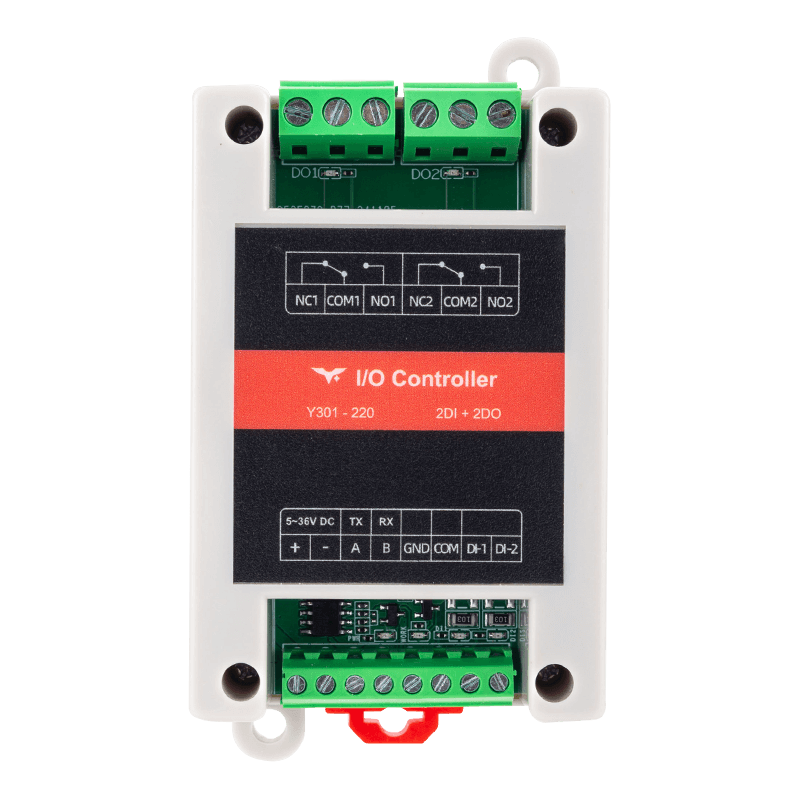 | 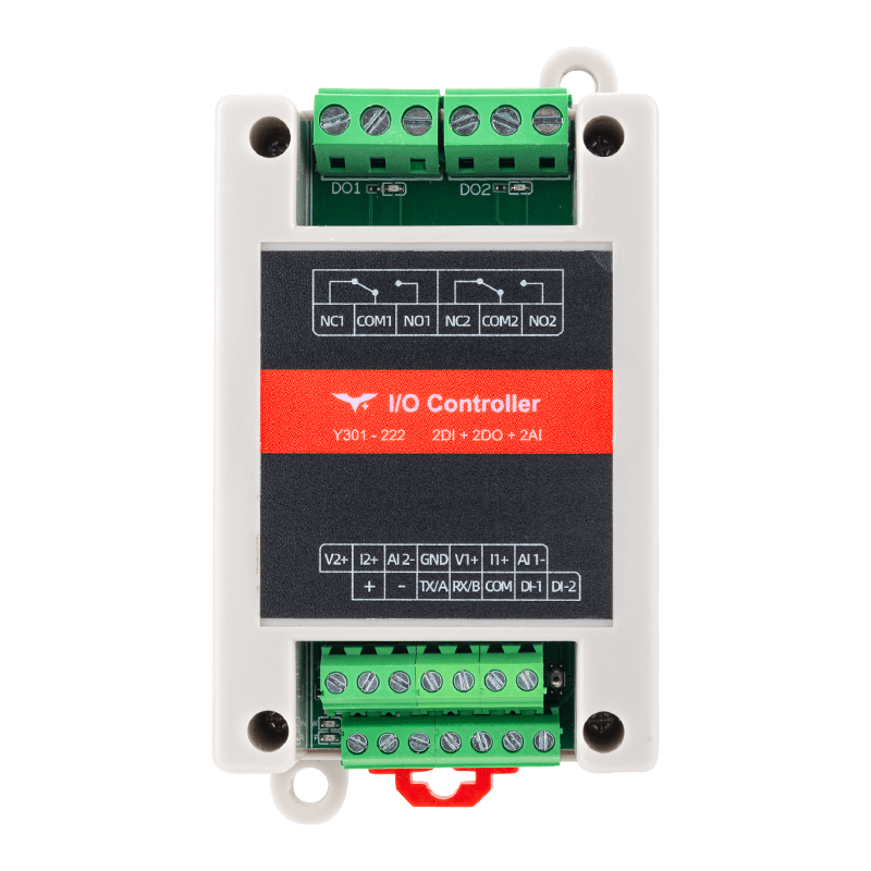 |
Contents
- Overview
- Default Settings
- Modbus Register Map (Modbus Address Only)
- Command Examples (CRC Included)
- Parameter Configuration
- Automation Rules
- Troubleshooting
1. Overview
This manual describes the Modbus RTU communication commands for the Y301-220 and Y301-222 I/O modules.
| Model | DI | DO | AI | Description |
|---|---|---|---|---|
| Y301-220 | 2 | 2 | 0 | Dual input + dual relay |
| Y301-222 | 2 | 2 | 2 | Dual input + dual relay + dual analog input |
Frame format: [slave address][function code][data][CRC low][CRC high]
The examples below use slave address 0x01. Replace it with the actual device address in your application.
2. Default Settings
| Parameter | Default |
|---|---|
| Slave address | 1 |
| Baud rate | 9600 bps |
| Data bits | 8 |
| Stop bits | 1 |
| Parity | None |
| Output state hold | Keep after soft reboot (0x0040 = 1) |
| Pulse counting edge | Rising edge (0x0041 = 1) |
| Pulse debounce | 50 ms (0x0042 = 50) |
3. Modbus Register Map (Modbus Address Only)
3.1 Digital Input (DI) - Function Code 0x02
| Channel | Modbus Address | R/W |
|---|---|---|
| DI1 | 0x0000 | RO |
| DI2 | 0x0001 | RO |
Return value: 0 = inactive, 1 = active.
3.2 Digital Output (DO) - Function Code 0x01/0x05/0x0F
| Channel | Modbus Address | R/W |
|---|---|---|
| DO1 | 0x0000 | RW |
| DO2 | 0x0001 | RW |
Write value: 0x0000 = open, 0xFF00 = closed.
3.3 Analog Input (AI) - Function Code 0x04 (Y301-222 only)
| Channel | Modbus Address | Description | Unit | R/W |
|---|---|---|---|---|
| AI1 voltage | 0x0000 | AI1 sampled voltage | mV | RO |
| AI1 current | 0x0001 | AI1 sampled current | uA | RO |
| AI2 voltage | 0x0002 | AI2 sampled voltage | mV | RO |
| AI2 current | 0x0003 | AI2 sampled current | uA | RO |
Each AI channel can be wired for either voltage or current. The other reading is invalid.
3.4 Common Holding Registers (Parameters) - Function Code 0x03/0x06/0x10
| Modbus Address | Parameter | Bytes | R/W | Range / Enum | Default |
|---|---|---|---|---|---|
0x002A | Runtime slave address (device addr + DIP offset) | 2 | RO | 0-255 | - |
0x002B | DIP offset address | 2 | RO | 0-31 | 0 |
0x003E | Slave address | 2 | RW | 1-255 | 1 |
0x003F | Broadcast mode | 2 | RW | 0=off, 1=recv+reply, 2=recv no reply | 0 |
0x0040 | Output state hold | 2 | RW | 0=no hold, 1=soft reboot hold, 2=soft reboot + power-on hold | 1 |
0x0041 | Pulse count edge | 2 | RW | 0=falling, 1=rising | 1 |
0x0042 | Pulse debounce (ms) | 2 | RW | 5-255 | 50 |
0x004C | Serial heartbeat period (s) | 2 | RW | 0=off, 1-65535 | 0 |
0x004D | Serial heartbeat payload | 16 | RW | string | - |
0x0055 | RTC Unix time | 4 | RW | uint32 | - |
0x0057 | Baud rate | 4 | RW | 600-230400 | 9600 |
0x0059 | Data bits | 2 | RW | 8, 9 | 8 |
0x005A | Stop bits | 2 | RW | 1, 2 | 1 |
0x005B | Parity | 2 | RW | 0=None, 1=Odd, 2=Even | 0 |
0x005C | Packet timeout (ms) | 2 | RW | 0-255 (0=adaptive) | 0 |
Notes:
- 32-bit values (for example
0x0055,0x0057) should be written in big-endian word order (high word first). - Per manufacturer behavior, changing serial parameters or slave address requires reboot to take effect.
3.5 DI Pulse Counter Registers (Holding Registers)
| Channel | Modbus Address | Bytes | R/W | Description |
|---|---|---|---|---|
| DI1 count | 0x0500 (uses 0x0500~0x0501) | 4 | RW | Only 0 is allowed for write (clear) |
| DI2 count | 0x0502 (uses 0x0502~0x0503) | 4 | RW | Only 0 is allowed for write (clear) |
3.6 Automation Rule Registers (Holding Registers)
Y301-220/222 has 2 DO channels, so total rule groups = DO * 2 = 4.
| Rule Group | Start Modbus Address | Length |
|---|---|---|
| Rule 1 | 0x0080 | 8 registers (16 bytes) |
| Rule 2 | 0x0088 | 8 registers (16 bytes) |
| Rule 3 | 0x0090 | 8 registers (16 bytes) |
| Rule 4 | 0x0098 | 8 registers (16 bytes) |
Single-group field structure:
| Offset | Field | Bytes |
|---|---|---|
+0 | Mode | 2 |
+1 | Action | 2 |
+2 | DO index | 2 |
+3 | DI/AI index | 2 |
+4~+5 | Parameter 1 | 4 |
+6~+7 | Parameter 2 | 4 |
3.7 Special Register
| Modbus Address | Name | Write Value | Description |
|---|---|---|---|
0x0800 | Reboot / Factory reset | 0x5500=reboot, 0x0055 or 0x5555=factory reset + reboot | WO |
4. Command Examples (CRC Included)
Tip: each command is shown in an individual code block. VitePress displays a copy icon on the top-right of every code block, so users can click once to copy the Modbus command.
4.1 Read Digital Inputs
| Operation | Request |
|---|---|
| Read DI1 | 01 02 00 00 00 01 B9 CA |
| Read DI2 | 01 02 00 01 00 01 E8 0A |
| Read DI1~DI2 in one shot | 01 02 00 00 00 02 F9 CB |
4.2 Read Digital Output Status
Query (0x01):
| Operation | Request |
|---|---|
| Read DO1 | 01 01 00 00 00 01 FD CA |
| Read DO2 | 01 01 00 01 00 01 AC 0A |
| Read DO1~DO2 in one shot | 01 01 00 00 00 02 BD CB |
Single-channel control (0x05):
| Operation | Request |
|---|---|
| Open DO1 | 01 05 00 00 00 00 CD CA |
| Close DO1 | 01 05 00 00 FF 00 8C 3A |
| Open DO2 | 01 05 00 01 00 00 9C 0A |
| Close DO2 | 01 05 00 01 FF 00 DD FA |
Multi-channel control (0x0F):
| Operation | Request |
|---|---|
| Close DO1 and DO2 together | 01 0F 00 00 00 02 01 03 9E 96 |
| Open DO1 and DO2 together | 01 0F 00 00 00 02 01 00 DE 97 |
4.3 Read Analog Inputs (Y301-222 only)
| Operation | Request |
|---|---|
| Read AI1 voltage | 01 04 00 00 00 01 31 CA |
| Read AI1 current | 01 04 00 01 00 01 60 0A |
| Read AI2 voltage | 01 04 00 02 00 01 90 0A |
| Read AI2 current | 01 04 00 03 00 01 C1 CA |
| Read AI1+AI2 (voltage+current, 4 regs) | 01 04 00 00 00 04 F1 C9 |
4.4 Parameter Read/Write (0x03/0x06/0x10)
Device address:
| Operation | Request |
|---|---|
Read slave address (0x003E) | 01 03 00 3E 00 01 E5 C6 |
| Write slave address = 5 | 01 06 00 3E 00 05 28 05 |
Serial parameters:
| Operation | Request |
|---|---|
Read baud rate (0x0057, 2 regs) | 01 03 00 57 00 02 75 DB |
Write baud rate = 115200 (0x0001C200) | 01 10 00 57 00 02 04 00 01 C2 00 B7 D5 |
Write baud rate = 9600 (0x00002580) | 01 10 00 57 00 02 04 00 00 25 80 AC 45 |
Read data/stop/parity (0x0059~0x005B) | 01 03 00 59 00 03 D5 D8 |
Write 8N1 | 01 10 00 59 00 03 06 00 08 00 01 00 00 85 EF |
State hold and count settings:
| Operation | Request |
|---|---|
Read output state hold (0x0040) | 01 03 00 40 00 01 85 DE |
| Write output state hold = 2 | 01 06 00 40 00 02 09 DF |
Read pulse edge (0x0041) | 01 03 00 41 00 01 D4 1E |
| Write pulse edge = 1 (rising) | 01 06 00 41 00 01 18 1E |
Read debounce (0x0042) | 01 03 00 42 00 01 24 1E |
| Write debounce = 50 ms | 01 06 00 42 00 32 A8 0B |
4.5 DI Pulse Counter Read/Write
| Operation | Request |
|---|---|
Read DI1 count (0x0500, 2 regs) | 01 03 05 00 00 02 C4 C7 |
Read DI2 count (0x0502, 2 regs) | 01 03 05 02 00 02 65 07 |
| Clear DI1 count (write 0) | 01 10 05 00 00 02 04 00 00 00 00 CC FF |
4.6 Special Operations
| Operation | Request |
|---|---|
Reboot (0x0800=0x5500) | 01 06 08 00 55 00 B4 FA |
Factory reset + reboot (0x0800=0x0055) | 01 06 08 00 00 55 4B 95 |
4.7 Copy-Ready Command Blocks
Commonly used commands are listed below as plain command blocks for one-click copy:
text
01 02 00 00 00 02 F9 CBtext
01 0F 00 00 00 02 01 03 9E 96text
01 04 00 00 00 04 F1 C9text
01 10 00 57 00 02 04 00 01 C2 00 B7 D55. Parameter Configuration
5.1 Runtime Slave Address
Runtime slave address = configured device address (0x003E) + DIP offset (0x002B).
For hardware versions without DIP offset support, 0x002B is usually 0, so runtime address equals device address.
5.2 Serial Settings
- Baud rate is stored at
0x0057as a 32-bit value, so use0x10to write 2 registers. - Data bit / stop bit / parity are located at
0x0059~0x005B. - Per manufacturer behavior, serial parameters and slave address require reboot to take effect.
5.3 Broadcast Mode (0x003F)
| Value | Meaning |
|---|---|
0 | Broadcast processing off |
1 | Receive and reply to broadcast |
2 | Receive but do not reply |
5.4 Output State Hold (0x0040)
| Value | Meaning |
|---|---|
0 | No hold |
1 | Hold after soft reboot |
2 | Hold after soft reboot and power-on reboot |
6. Automation Rules
6.1 Supported Modes
| Mode | Name | Description |
|---|---|---|
| 0 | Disabled | Rule is disabled |
| 1 | DI follow | DO follows DI (normal/inverse by action) |
| 2 | Pulse output | DO returns after delay |
| 3 | Delayed control | Open/close/all actions delayed |
| 4 | Timed change | Execute once after delay from reboot |
| 5 | Cyclic change | Toggle by parameter1/parameter2 cycle |
| 6 | Button (jog) | DI works as a button to trigger DO |
| 7 | Fixed-point one-shot | Execute once at target Unix time |
| 8 | Fixed-point cyclic | Repeat by interval from target time |
| 9 | Daily schedule | Execute every day at target second-of-day |
| 10 | AI voltage > threshold | Y301-222 only |
| 11 | AI voltage < threshold | Y301-222 only |
| 12 | AI current > threshold | Y301-222 only |
| 13 | AI current < threshold | Y301-222 only |
| 14 | Delayed follow | Follow DI after delay |
| 15 | Logical AND | Multi-channel DI/DO AND logic |
| 16 | Logical OR | Multi-channel DI/DO OR logic |
| 17 | Logical XOR | Multi-channel DI/DO XOR logic |
6.2 Rule Command Examples
All examples below write to Rule 1 (start 0x0080) with slave address 0x01.
For Rule 2/3/4, replace start address with 0x0088 / 0x0090 / 0x0098 and recalculate CRC.
Action code reference: 0=open, 1=close, 2=toggle (depends on mode).
- Case 1: DI Follow (Mode 1): DO1 follows DI1
| Field | Value | Description |
|---|---|---|
| Mode | 0x0001 | DI follow |
| Action | 0x0001 | Forward follow (close when DI=1) |
| DO index | 0x0001 | DO1 |
| DI/AI index | 0x0001 | DI1 |
| Parameter 1 | 0x00000000 | Not used |
| Parameter 2 | 0x00000000 | Not used |
text
01 10 00 80 00 08 10 00 01 00 01 00 01 00 01 00 00 00 00 00 00 00 00 CC FE- Case 2: AI Voltage > Threshold (Mode 10): if AI1 > 5V, open DO1
| Field | Value | Description |
|---|---|---|
| Mode | 0x000A | AI voltage greater than threshold |
| Action | 0x0000 | Open |
| DO index | 0x0001 | DO1 |
| DI/AI index | 0x0001 | AI1 |
| Parameter 1 | 0x00001388 | Threshold 5000 mV (= 5 V) |
| Parameter 2 | 0x000003E8 | Execution interval 1000 ms (debounce) |
text
01 10 00 80 00 08 10 00 0A 00 00 00 01 00 01 00 00 13 88 00 00 03 E8 67 7A- Case 3: AI Voltage < Threshold (Mode 11): if AI1 < 2V, close DO1
| Field | Value | Description |
|---|---|---|
| Mode | 0x000B | AI voltage lower than threshold |
| Action | 0x0001 | Close |
| DO index | 0x0001 | DO1 |
| DI/AI index | 0x0001 | AI1 |
| Parameter 1 | 0x000007D0 | Threshold 2000 mV (= 2 V) |
| Parameter 2 | 0x000003E8 | Execution interval 1000 ms |
text
01 10 00 80 00 08 10 00 0B 00 01 00 01 00 01 00 00 07 D0 00 00 03 E8 86 22Detailed breakdown for this case (later examples follow the same pattern):
| Byte Sequence | Meaning |
|---|---|
01 | Slave address = 0x01 |
10 | Function code = 0x10 (Write Multiple Holding Registers) |
00 80 | Start register = 0x0080 (Rule 1 base address) |
00 08 | Register count = 8 (16-byte rule payload) |
10 | Byte count = 16 |
00 0B | Mode = 0x000B (AI voltage lower than threshold) |
00 01 | Action = 0x0001 (close) |
00 01 | DO index = 1 (DO1) |
00 01 | DI/AI index = 1 (AI1) |
00 00 07 D0 | Parameter 1 = 2000 mV = 2.0V threshold |
00 00 03 E8 | Parameter 2 = 1000 ms trigger interval / debounce |
86 22 | CRC16 (low byte first) |
Meaning summary: this writes a rule to Rule 1 so that when AI1 voltage is lower than 2V, DO1 closes, with a minimum execution interval of 1000 ms.
- Case 4: AI Current > Threshold (Mode 12): if AI1 > 10mA, close DO1
| Field | Value | Description |
|---|---|---|
| Mode | 0x000C | AI current greater than threshold |
| Action | 0x0001 | Close (turn on) |
| DO index | 0x0001 | DO1 |
| DI/AI index | 0x0001 | AI1 |
| Parameter 1 | 0x00002710 | Threshold 10000 uA (= 10 mA) |
| Parameter 2 | 0x000003E8 | Execution interval 1000 ms (debounce) |
text
01 10 00 80 00 08 10 00 0C 00 01 00 01 00 01 00 00 27 10 00 00 03 E8 C6 51- Case 5: AI Current < Threshold (Mode 13): if AI1 < 4mA, open DO1
| Field | Value | Description |
|---|---|---|
| Mode | 0x000D | AI current lower than threshold |
| Action | 0x0000 | Open |
| DO index | 0x0001 | DO1 |
| DI/AI index | 0x0001 | AI1 |
| Parameter 1 | 0x00000FA0 | Threshold 4000 uA (= 4 mA) |
| Parameter 2 | 0x000003E8 | Execution interval 1000 ms |
text
01 10 00 80 00 08 10 00 0D 00 00 00 01 00 01 00 00 0F A0 00 00 03 E8 42 22- Case 6: Pulse Output (Mode 2): DO1 normally open, auto-recover after 2s close
| Field | Value | Description |
|---|---|---|
| Mode | 0x0002 | Pulse output |
| Action | 0x0000 | Normally open |
| DO index | 0x0001 | DO1 |
| DI/AI index | 0x0000 | Not used |
| Parameter 1 | 0x000007D0 | Pulse duration 2000 ms |
| Parameter 2 | 0x00000000 | Not used |
text
01 10 00 80 00 08 10 00 02 00 00 00 01 00 00 00 00 07 D0 00 00 00 00 40 8B- Case 7: Delayed Control (Mode 3): DO1 open command delayed by 3s
| Field | Value | Description |
|---|---|---|
| Mode | 0x0003 | Delayed control |
| Action | 0x0000 | Delayed open only |
| DO index | 0x0001 | DO1 |
| DI/AI index | 0x0000 | Not used |
| Parameter 1 | 0x00000BB8 | Delay 3000 ms |
| Parameter 2 | 0x00000000 | Not used |
text
01 10 00 80 00 08 10 00 03 00 00 00 01 00 00 00 00 0B B8 00 00 00 00 E0 8E- Case 8: Cyclic Change (Mode 5): DO1 open 1s, close 2s in cycle
| Field | Value | Description |
|---|---|---|
| Mode | 0x0005 | Cyclic change |
| Action | 0x0000 | Open first |
| DO index | 0x0001 | DO1 |
| DI/AI index | 0x0000 | Not used |
| Parameter 1 | 0x000003E8 | Open duration 1000 ms |
| Parameter 2 | 0x000007D0 | Close duration 2000 ms |
text
01 10 00 80 00 08 10 00 05 00 00 00 01 00 00 00 00 03 E8 00 00 07 D0 A4 64- Case 9: Button/Jog (Mode 6): DI1 button toggles DO1
| Field | Value | Description |
|---|---|---|
| Mode | 0x0006 | Button (jog) |
| Action | 0x0002 | Toggle |
| DO index | 0x0001 | DO1 |
| DI/AI index | 0x0001 | DI1 as button input |
| Parameter 1 | 0x000003E8 | Press duration 1000 ms |
| Parameter 2 | 0x00000000 | Not used |
text
01 10 00 80 00 08 10 00 06 00 02 00 01 00 01 00 00 03 E8 00 00 00 00 EE 1B- Case 10: Logical AND (Mode 15): DO1 close only when DO2=close and DI1+DI2=active
| Field | Value | Description |
|---|---|---|
| Mode | 0x000F | Logical AND |
| Action | 0x0004 | Close (hold) |
| DO index | 0x0001 | DO1 |
| DI/AI index | 0x0000 | Not used |
| Parameter 1 | 0x00000002 | DO2 participates in logic (bit1=1) |
| Parameter 2 | 0x00000003 | DI1+DI2 participate in logic (bit0+bit1=1) |
text
01 10 00 80 00 08 10 00 0F 00 04 00 01 00 00 00 00 00 02 00 00 00 03 7A AE- Case 11: Timed Change (Mode 4): after reboot, close DO1 in 5s
| Field | Value | Description |
|---|---|---|
| Mode | 0x0004 | Timed change |
| Action | 0x0001 | Close |
| DO index | 0x0001 | DO1 |
| DI/AI index | 0x0000 | Not used |
| Parameter 1 | 0x00001388 | Timer 5000 ms |
| Parameter 2 | 0x00000000 | Not used |
text
01 10 00 80 00 08 10 00 04 00 01 00 01 00 00 00 00 13 88 00 00 00 00 E6 D1- Case 12: Daily Schedule (Mode 9): open DO1 every day at 18:00:00
| Field | Value | Description |
|---|---|---|
| Mode | 0x0009 | Daily schedule |
| Action | 0x0000 | Open |
| DO index | 0x0001 | DO1 |
| DI/AI index | 0x0000 | Not used |
| Parameter 1 | 0x0000FD20 | Seconds of day 64800 (18x3600) |
| Parameter 2 | 0x00000000 | Not used |
text
01 10 00 80 00 08 10 00 09 00 00 00 01 00 00 00 00 FD 20 00 00 00 00 5F C3Note: modes 7~9 depend on RTC time. After reboot, write current Unix timestamp to RTC register
0x0055first.
7. Troubleshooting
| Symptom | Cause | Solution |
|---|---|---|
| No response | Wrong address or baud rate | Check settings and try broadcast address 0 |
| CRC error | Wiring issue or interference | Check RS485 polarity and add termination resistors |
| DO does not switch | Load exceeds rating | Reduce the load and verify contact ratings |
| DI always reads 0 | Wiring error | Check COM/DI wiring and input voltage |
| AI reading is abnormal | Wrong wiring mode | Verify voltage/current wiring; each channel supports only one mode at a time |
LED Indicators
| LED | Status | Meaning |
|---|---|---|
| POWER | Solid on | Power is normal |
| TX | Flashing | Data is being transmitted |
| RX | Flashing | Data is being received |
| DI1/DI2 | On | Input is active |
| DO1/DO2 | On | Relay is closed |
- Manufacturer: Hunan YenGear Tech Co., Ltd.
- Email: [email protected]
- Website: www.yengear.com