
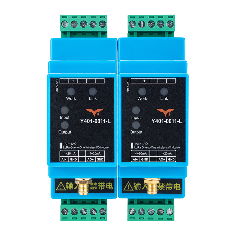
Appearance
Y401-0011-L LoRa Wireless Analog I/O Synchronization Module Datasheet
Contents
- Overview
- Ordering Information
- Key Features
- Technical Specifications
- Interfaces and Indicators
- Mechanical and Environmental
- Installation and Wiring
- Important Notes
1. Overview
The Y401-0011-L is a single-channel point-to-point wireless analog I/O terminal based on LoRa modulation. A standard system uses two factory-paired modules, Device A and Device B. Each module provides one 4-20 mA analog input and one 4-20 mA analog output.
Each analog input at one device is transmitted over the wireless link and reproduced as the corresponding 4-20 mA analog output at the other device. The same signal paths can operate in the reverse direction. The wireless link is half-duplex.
Signal Mapping
| Direction | Signal path |
|---|---|
| Device A to Device B | Device A AI1 -> wireless link -> Device B AO1 |
| Device B to Device A | Device B AI1 -> wireless link -> Device A AO1 |
Typical Applications
- Remote 4-20 mA signal extension
- Industrial equipment monitoring and control
- Agricultural and aquaculture monitoring
- Hydrological monitoring and early warning
- Transportation and community infrastructure monitoring
- Remote equipment signal transmission, including rolling-door control
2. Ordering Information
Model Configuration
Y401-0011-L is a one-to-one LoRa analog pair with no digital I/O. According to the hardware specification, each device provides one AI channel and one AO channel.
For the full code and examples, see Model Naming.
Channel Configuration
| Digital input | Digital output | Analog input | Analog output |
|---|---|---|---|
| 0 | 0 | 1 | 1 |
System Configuration
A standard Y401-0011-L wireless link uses two factory-paired modules: Device A and Device B. No on-site configuration is required for normal operation after the modules are connected to power and wired to the field circuits.
3. Key Features
- One analog input and output - 1 x 4-20 mA input and 1 x 4-20 mA output per module
- Bidirectional point-to-point transfer - The two paired devices can transfer analog signals in either direction
- Long-range communication - Up to 5 km standard in open areas; a 10 km option is available for selected configurations
- Plug-and-play deployment - Factory paired and ready to use without on-site configuration
- Wide supply range - 9 to 36V DC with reverse-polarity protection
- Active analog outputs - 1 x 4-20 mA constant-current output for loads of up to 500 ohms
- Status indication - LEDs for system operation, link, input current, and output current
- Industrial installation - Hardware watchdog, 5.08 mm pitch pluggable terminals, and 35 mm DIN rail mounting
4. Technical Specifications
Wireless
| Parameter | Specification |
|---|---|
| Modulation | LoRa |
| Frequency band | 398 to 525 MHz |
| Communication range | Up to 5 km standard; 10 km option available for selected configurations; actual range depends on antenna installation, obstructions, interference, and site conditions |
| Antenna connector | SMA |
| Antenna option | 470 MHz magnetic-mount antenna |
| Communication mode | Half-duplex |
Electrical
| Parameter | Specification |
|---|---|
| Supply voltage | 9 to 36V DC |
| Max. power consumption | Approx. 2W |
| Analog input | 1 x 4-20 mA active current input |
| Input source requirement | Active current source with a source voltage of at least 10V |
| Input current limit | Imax ≤ 24 mA |
| Input acquisition accuracy | ≤ ±0.3 mA |
| Analog output | 1 x 4-20 mA active constant-current output |
| Output error | ≤ ±0.3 mA |
| Maximum stated load | ≤ 500 ohms; verify the supply-voltage and load combination before use |
Interfaces
| Parameter | Specification |
|---|---|
| Field terminals | 5.08 mm pitch pluggable terminals |
| Installation | 35 mm DIN rail |
5. Interfaces and Indicators
Interface Summary
| Interface | Description |
|---|---|
| Antenna | SMA connector for the LoRa antenna |
| Power | DC 9 to 36V input; observe the polarity markings on the device |
| Analog input | One active 4-20 mA current input; connect each signal between its input positive terminal and the input ground/negative terminal |
| Analog output | One active 4-20 mA constant-current output; connect each output between its positive terminal and the output ground/negative terminal |
| Field terminals | 5.08 mm pitch pluggable terminals |
The wiring diagrams mark the negative sides of the analog input and output as ground. Do not assume galvanic isolation between the power, input, and output circuits without a confirmed electrical diagram.
LED Indicators
| LED | Function | Status |
|---|---|---|
| Work | System operating status | On after the system starts |
| Link | Wireless link status | On when the paired device is connected; flashing indicates abnormal communication; off when disconnected |
| Input | Analog input status | On when an input current signal is detected |
| Output | Analog output status | On when the module is producing an output current |
6. Mechanical and Environmental
Mechanical Specifications
| Parameter | Specification |
|---|---|
| Dimensions | 58.7 × 111.2 × 36.5 mm |
| Weight | Approx. 350 g |
| Mounting | 35 mm DIN rail |
Environmental Specifications
| Parameter | Specification |
|---|---|
| Operating temperature | -20 to +75 °C |
| Operating humidity | 10% to 90% RH, non-condensing |
7. Installation and Wiring
Power Wiring
- Use a regulated DC power supply rated from 9 to 36V.
- Connect the positive and negative terminals according to the polarity markings on the device.
- Confirm the supply voltage before power-up. Low voltage may prevent the device from starting.
Analog Input Wiring
The analog inputs accept active 4-20 mA current signals. Each external signal source must provide a current-source voltage of at least 10V. The Y401-0011-L inputs are not specified as a sensor loop power supply.
The three wiring patterns below show one representative input channel of a single-channel Y401-0011-L link. Each module requires DC power within its rated range. The diagrams use a 24V supply for the field transmitter or signal generator and a 9 to 36V supply for the output-side module as examples. The field supply may vary when it meets the transmitter requirements and the analog input source requirement of at least 10V; each module power supply must remain within the 9 to 36V DC rating.
Two-Wire Transmitter

A two-wire current transmitter uses the same two wires for its power supply and 4-20 mA signal loop. Use an external loop supply, such as the 24V example shown in the wiring diagram.
- Connect the loop supply positive to the transmitter positive terminal.
- Connect the transmitter current-return terminal to the Y401-0011-L analog input positive terminal.
- Connect the Y401-0011-L analog input ground/negative terminal to the loop supply negative.
- Power the receiving Y401-0011-L module within its 9 to 36V DC rating and connect its active analog output to the receiving current input.
Three-Wire Transmitter

A three-wire current transmitter has one positive power wire and two signal wires, with one signal wire shared with the power ground. The supplied example identifies the wires as signal output, DC24V negative, and DC24V positive.
- Connect the transmitter power positive to the external transmitter supply positive.
- Connect the transmitter common ground to the external supply negative and the Y401-0011-L analog input ground/negative.
- Connect the transmitter signal output to the Y401-0011-L analog input positive terminal.
- Power the receiving Y401-0011-L module within its 9 to 36V DC rating and connect its active analog output to the receiving current input.
Four-Wire Transmitter or Signal Generator

A four-wire current device uses two power wires and two separate signal wires. The supplied example labels the instrument terminals as OUT for signal positive, G for signal negative, V+ for power positive, and G for power negative.
- Connect the instrument power positive and power negative to the external instrument supply.
- Connect the instrument signal positive to the Y401-0011-L analog input positive terminal.
- Connect the instrument signal negative to the Y401-0011-L analog input ground/negative terminal.
- Power the receiving Y401-0011-L module within its 9 to 36V DC rating and connect its active analog output to the receiving current input.
For all three arrangements:
- Follow the field instrument's terminal labels and polarity markings. Wire colors in an example diagram are not a universal terminal standard.
- Use an active current source. The analog input does not provide transmitter excitation unless the final electrical design explicitly confirms it.
- Connect the input signal positive and negative terminals only as shown by the instrument's wiring requirements.
Current input only
Do not connect a voltage signal or an external voltage source directly to the analog input. Confirm the transmitter wiring and polarity before applying power.
Analog Output Wiring
The analog outputs are active 4-20 mA constant-current sources. Connect each output to a compatible passive analog input or current receiver. Keep each receiving load at or below 500 ohms, subject to the available supply voltage and the actual output compliance requirement.
The three-wire example shows a current meter with a 150 ohm series resistor. The two-wire example uses a multimeter in DC current mode; the four-wire example uses a separately powered current indicator. Use the resistor value required by the receiving instrument and include it in the total loop load; 150 ohms is an example, not a universal requirement.
Module terminal positions in these diagrams are schematic; use the markings on the actual device.
Do not connect the active output directly to another active current source or treat it as a voltage output.
Wireless Installation
- Install the antenna vertically in an open area, about 2 m above ground when possible.
- Keep the antenna away from large metal structures and do not install it inside a metal cabinet.
- Tighten the SMA connector securely.
- Mount the module on a stable 35 mm DIN rail.
- Keep the module away from direct sunlight, heat sources, liquids, heavy dust, smoke, and strong sources of radio interference.
8. Important Notes
- Half-duplex communication - The wireless link is not a simultaneous full-duplex connection. It is not intended for applications that require high real-time performance, especially in complex radio environments.
- Range planning - The 5 km value is an open-area reference. A 10 km option requires the specified configuration and antenna. Confirm the antenna, mounting height, obstructions, interference, and site conditions before committing to a range.
- Analog accuracy - The specified ±0.3 mA input accuracy and output error are product limits. Confirm the required accuracy before using the module for measurement or closed-loop control.
- Output load - A 20 mA current through a 500 ohm load requires 10V across the load before wiring and device headroom are considered. Confirm the supply-voltage and load combination, especially when operating near the 9V lower supply limit.
- Signal failure behavior - The analog output fault state after a wireless link loss is not defined in this datasheet. Do not use the module as the sole control or safety path; validate the complete system before closed-loop use.
- Safety boundary - Do not use the wireless link as the sole path for emergency-stop, personnel-safety, or other safety functions.
- Installation environment - Do not install the device in explosive, wet, dusty, smoky, or strongly interference-prone environments. Use a proper power adapter and do not disassemble the device.
- Manufacturer: Hunan YenGear Tech Co., Ltd.
- Address: Room 21014, Building 1, Fudi Xingguang Tiandi, Yingxin Road, Yuhua District, Changsha, Hunan, China
- Email: [email protected]
- Website: www.yengear.com