
Appearance
Y412-22/44/88-L Wireless I/O Module Datasheet
| Y412-22-L (2-channel) | Y412-44-L (4-channel) | Y412-88-L (8-channel) |
|---|---|---|
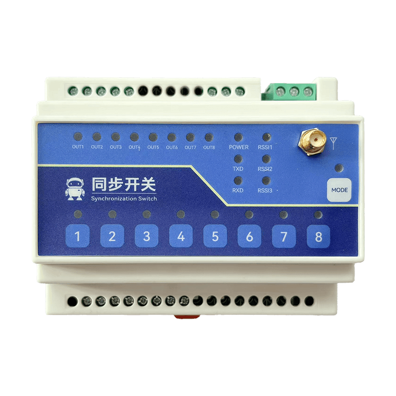 | 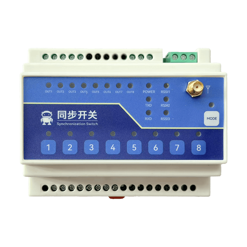 | 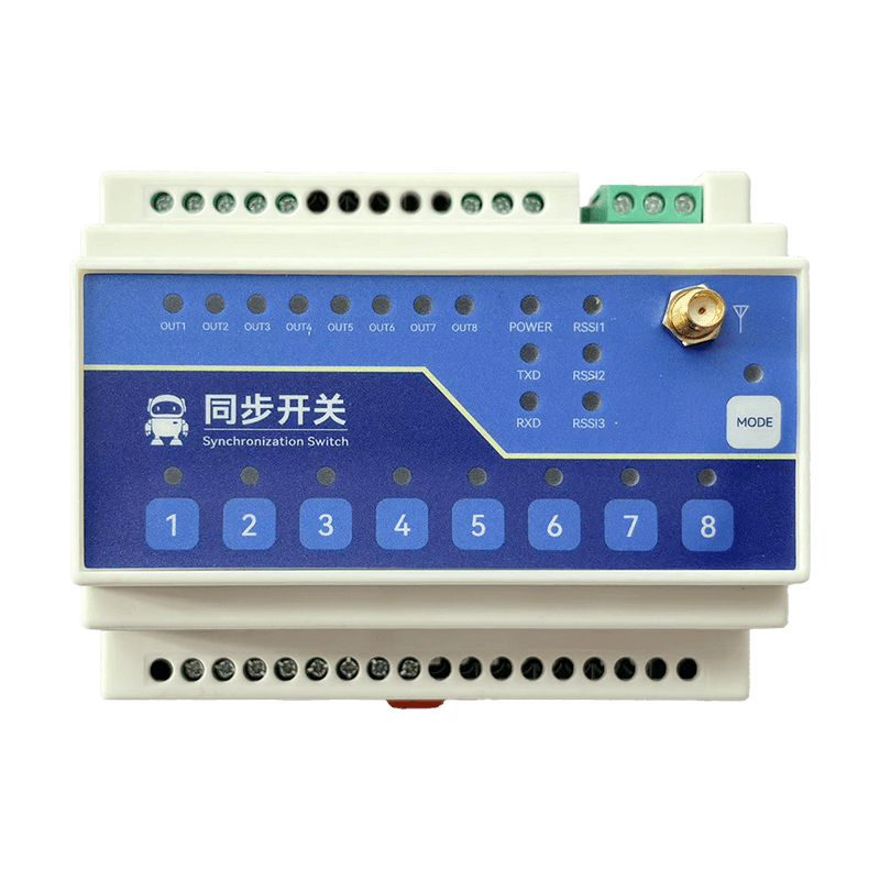 |
Contents
- Overview
- Ordering Information
- Key Features
- Technical Specifications
- Interfaces and Indicators
- Mechanical and Environmental
- Installation and Wiring
- Important Notes
1. Overview
The Y412 series is a LoRa-based Wireless I/O Module family for dry-contact input acquisition and relay output control. It is designed for fast field deployment with minimal setup and is a practical replacement for long cross-area control wiring.
Y412-22-L: 2DI / 2DOY412-44-L: 4DI / 4DOY412-88-L: 8DI / 8DO
The series supports master/slave mode, bidirectional follow or unidirectional feedback, and momentary or latching control. Typical applications include pump and valve interlock, lighting group control, and remote start/stop.
2. Ordering Information
Model Naming
text
Y412-XX-L
  |   |  `-- L: LoRa wireless communication
  |   `----- XX: channel count (22 / 44 / 88)
  `--------- Y412: wireless I/O module series
Model Matrix
| Model | DI Channels | DO Channels | Description |
|---|---|---|---|
| Y412-22-L | 2 | 2 | Dual-channel Wireless I/O Module |
| Y412-44-L | 4 | 4 | Four-channel Wireless I/O Module |
| Y412-88-L | 8 | 8 | Eight-channel Wireless I/O Module |
3. Key Features
- 2 / 4 / 8-channel options - Common control logic across the series for easy model selection
- Long-range wireless link - LoRa modulation with up to 5 km standard in open areas; a 10 km option is available for selected configurations
- Minimal setup - Default DIP settings allow fast commissioning, with channel and mode selection handled on site
- Multiple operating modes - Supports master/slave, unidirectional or bidirectional behavior, and momentary or latching output control
- Local push-buttons - Each channel includes a local key for commissioning and emergency operation
- Dry contact / NPN input - Compatible with push-buttons, relay contacts, and common sensor outputs
- Form A relay output - Contact rating up to
5A @ 250VACor5A @ 30VDC - DIN rail mounting - Standard 35 mm DIN rail format for control cabinet installation
4. Technical Specifications
Wireless
| Parameter | Specification |
|---|---|
| Operating frequency | 410.125 to 493.125 MHz (ISM) |
| Transmit power | 30 dBm (max. approx. 1W) |
| Receiver sensitivity | -148 dBm @ 2.4 Kbps |
| Max. range | 5 km standard; 10 km option available for selected configurations |
| Channels | 32 (set by DIP switches 1 to 5) |
| Air data mode | Range priority (default) / balanced / response priority |
| Antenna connector | SMA |
Electrical
| Parameter | Specification |
|---|---|
| Supply (DC version) | 8 to 28V DC |
| Supply (AC version) | 85 to 265V AC |
| Average current | 70 mA @ 12V DC |
| TX current | 290 mA @ 12V DC |
| Current per energized relay | 15 mA @ 12V DC |
| DI input type | Dry contact / NPN |
| DO output type | Form A relay (NO + COM) |
| Relay contact rating | 5A 30V DC / 5A 250V AC |
5. Interfaces and Indicators
Port Description
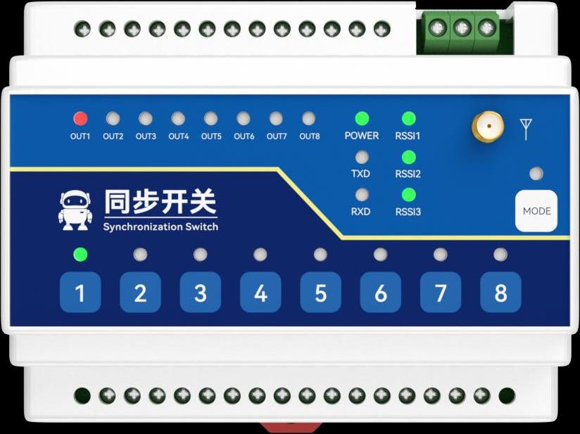
DI: digital input terminals (2 / 4 / 8 channels, depending on model)COM: common terminal for DIDO COM: relay common terminalDO NO: relay normally open terminalRS485 A/B/G: configuration and commissioning interface- Power terminals:
- DC version:
V+ / V- / PE - AC version:
L / N / PE
- DC version:
LED Indicators
| LED | Color | Description |
|---|---|---|
| OUT1 to OUT8 | Red | Relay output status for each channel |
| POWER | Green | Power status |
| TXD / RXD | Green | Wireless transmit / receive activity |
| RSSI1 to RSSI3 | Green | Signal strength level |
| MODE | Blue | Mode or encryption status |
6. Mechanical and Environmental
Mechanical Specifications
| Parameter | Y412-22-L | Y412-44-L | Y412-88-L |
|---|---|---|---|
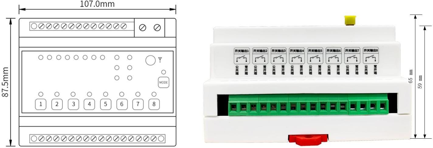
| Dimensions | 108 x 87.5 x 65 mm | 108 x 87.5 x 65 mm | 108 x 87.5 x 65 mm |
| Weight (DC) | 184 g +/- 5 g | 196 g +/- 5 g | 226 g +/- 5 g |
| Weight (AC) | 194 g +/- 5 g | 206 g +/- 5 g | 236 g +/- 5 g |
| Operating temperature | -40 to +85 degC | -40 to +85 degC | -40 to +85 degC |
| Operating humidity | 5% to 95% RH, non-condensing | 5% to 95% RH, non-condensing | 5% to 95% RH, non-condensing |
| Storage temperature | -60 to +125 degC | -60 to +125 degC | -60 to +125 degC |
| Storage humidity | 5% to 95% RH, non-condensing | 5% to 95% RH, non-condensing | 5% to 95% RH, non-condensing |
| Mounting | 35 mm DIN rail | 35 mm DIN rail | 35 mm DIN rail |
7. Installation and Wiring
Power Wiring
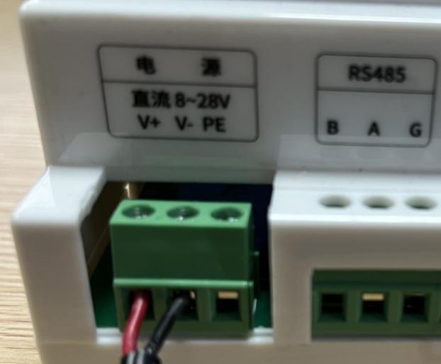
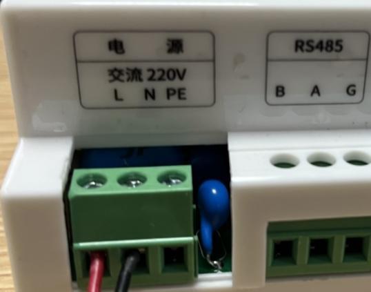
- DC version: connect
V+to positive,V-to negative, andPEto protective earth - AC version: connect
Lto live,Nto neutral, andPEto protective earth
DI Wiring
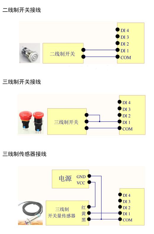
Supports 2-wire switches, 3-wire switches, and 3-wire sensors.
Installation Recommendations
- Keep the same channel setting on all devices in the same communication group (DIP switches 1 to 5).
- Keep the antenna away from large metal surfaces and strong interference sources.
- Complete power and antenna wiring before setting the mode DIP switches.
- For first-time deployment, validate a two-device link first, then expand to one-master/multi-slave operation.
8. Important Notes
- DIP-based commissioning - The Y412 series is mainly configured through DIP switches and local keys. For field setup, refer to the User Manual.
- Group consistency - Devices in the same group should use the same channel and key operating mode, otherwise linkage may fail.
- Range vs. response - Response-priority mode provides faster action with shorter range, while range-priority mode favors distance.
- Advanced parameters - Timeout reset and host-side parameters can be configured through RS485 or serial tools when required.
- Manufacturer: Hunan YenGear Tech Co., Ltd.
- Address: Room 21014, Building 1, Fudi Xingguang Tiandi, Yingxin Road, Yuhua District, Changsha, Hunan, China
- Email: [email protected]
- Website: www.yengear.com