
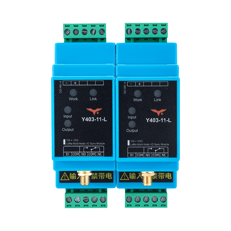
Appearance
Y403-11-L LoRa Auto Relay Wireless I/O Module Datasheet
Contents
- Overview
- Ordering Information
- Key Features
- Technical Specifications
- Interfaces and Indicators
- Mechanical and Environmental
- Installation and Wiring
- Important Notes
1. Overview
The Y403-11-L is a LoRa-based Auto Relay Wireless I/O Module. Equal-status nodes automatically select a communication path and forward switching signals to other nodes, extending the practical communication path. It is suited to coordinated auxiliary control and signalling such as distributed alarm annunciation and tunnel lighting; it is not a certified emergency-stop or personnel-safety system.
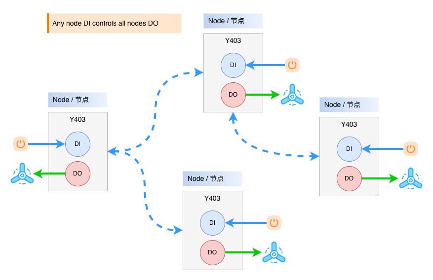
Operating Logic
- When the
DIon any node is closed, theDOon all nodes, including the local node, energizes - The outputs on all nodes reset only after the
DIon every node returns to open - Auto Relay nodes select the best route and forward signals to extend communication distance
Typical Applications
Auxiliary alarm annunciation, tunnel lighting control, underground facility monitoring, and coordinated non-safety equipment control
2. Ordering Information
Model Configuration
Y403-11-L is an Auto Relay LoRa module with 1 DI and 1 DO per node. Nodes have equal status and automatically forward signals.
For the full code and examples, see Model Naming.
Package Contents
| Qty. | Item |
|---|---|
| 1 | Y403-11-L module |
| 1 | 470 MHz magnetic-mount antenna |
| 1 | DIN rail clip |
| 1 | Quick reference guide |
| 1 | Warranty card |
3. Key Features
- Automatic relay forwarding - Nodes automatically select the best communication path and forward signals
- Interlocking control - A trigger from any node drives all linked nodes, including the local node
- OR logic output - All outputs reset only when every node input returns to open
- Long-range communication - Up to 5 km per hop standard in open areas; a 10 km option is available for selected configurations, with relay-based range extension
- Scalable expansion - Supports node expansion through Auto Relay forwarding
- Wide supply range - 9 to 36V DC with reverse-polarity protection
- Relay output - 1 x SPDT relay, rated at AC 277V 5A / DC 28V 5A
- Dry contact / NPN DI - Supports passive dry contacts and NPN open-collector inputs
- Status indication - LEDs for power, relay link, input, and output status
- Industrial design - Hardware watchdog and 35 mm DIN rail mounting
4. Technical Specifications
Wireless
| Parameter | Specification |
|---|---|
| Frequency band | 398 to 525 MHz |
| Communication range | Up to 5 km per hop standard; 10 km option available for selected configurations |
| Relay extension | Extended through node-to-node relaying |
| Antenna connector | SMA |
| Standard antenna | 470 MHz magnetic-mount antenna |
Electrical
| Parameter | Specification |
|---|---|
| Supply voltage | 9 to 36V DC |
| Max. power consumption | 1W |
| Input type | Passive dry contact / NPN open-collector (no voltage input to DI) |
| Output type | SPDT relay |
| Output rating | AC 277V 5A / DC 28V 5A |
| Operating temperature | -20 to +85 degC |
| Operating humidity | 10% to 90% RH, non-condensing |
5. Interfaces and Indicators
Interface Summary
| Interface | Description |
|---|---|
| Antenna | SMA connector for LoRa antenna |
| Power | DC 9 to 36V input with reverse-polarity protection |
| Input | Passive switch input (DI + COM) |
| Output | Relay output (NO + COM + NC) |
LED Indicators
| LED | Function | Status |
|---|---|---|
| Power | System status | On after power-up |
| Network | Relay link status | On when the relay communication link is established |
| Input | Input status | On when DI is closed |
| Output | Output status | On when the relay is energized |
6. Mechanical and Environmental
Mechanical Specifications
| Parameter | Specification |
|---|---|
| Dimensions | 88 x 37 x 59 mm |
| Weight | Approx. 50 g |
| Mounting | 35 mm DIN rail |
| Protection rating | IP20 |
| Housing material | Flame-retardant plastic |
7. Installation and Wiring
Input Wiring
No voltage input on DI
The digital input (DI) is not a voltage-input terminal. It is strictly forbidden to connect any powered signal or voltage source to DI.
Correct wiring: connect only a passive dry contact or an NPN open-collector output between DI and COM. Do not connect sensor power, PLC voltage output, or any external voltage directly to DI.
Mechanical switches (maintained switch, float switch, relay contact):
- Connect directly between
DIandCOM - No external power supply is required
NPN open-collector output:
- Output transistor collector ->
DI - Output transistor emitter / 0V reference ->
COM - Do not connect sensor power or any voltage output to
DI
Output Wiring
Direct load (<= 1 kW resistive load):
- Wire the load in series with the relay output
High-power load (> 1 kW):
- Use an AC contactor or external power relay
Installation Notes
- Install the antenna vertically in an open area, about 2 m above ground.
- Keep the unit away from large metal structures.
- Tighten the antenna connector securely.
- Mount the unit inside the control cabinet on a 35 mm DIN rail.
- Position nodes strategically to achieve the best automatic relay coverage.
- Leave enough space for ventilation.
Relay Expansion
- Nodes automatically select the best communication path and can relay traffic for other nodes.
- New nodes can join the existing automatic relay system without complex manual setup.
- Direct node-to-node range is up to 5 km per hop as a standard planning value; a 10 km option is available for selected configurations, with longer reach available through relay paths.
8. Important Notes
- Communication mode - Half-duplex communication, not intended for hard real-time control.
- Frequency range - Recommended operating range is 398 to 525 MHz. Performance may degrade outside this range.
- Antenna placement - Install the antenna vertically in an open area and keep it away from metal obstructions.
- Relay latency - Multi-hop relay paths may introduce additional delay. Confirm timing requirements before deployment.
- Interlocking logic - All node outputs reset only after every node input returns to open.
- Manufacturer: Hunan YenGear Tech Co., Ltd.
- Address: Room 21014, Building 1, Fudi Xingguang Tiandi, Yingxin Road, Yuhua District, Changsha, Hunan, China
- Email: [email protected]
- Website: www.yengear.com