
Appearance
Y408-WG-L Point-to-Point Wireless Wiegand Module User Manual
Applicable model: Y408-WG-L.
Product Introduction
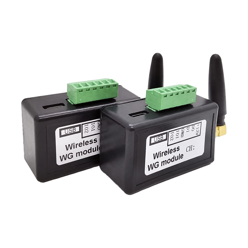
The Y408-WG-L sends Wiegand reader data over a point-to-point wireless link. Use the standard matched pair of two modules for a complete installation. D0 and D1 are the primary data path; IO1 and IO2 are optional auxiliary I/O for compatible feedback or button functions.
Main features:
- Automatic WG26 to WG80 recognition, including keypad data
- 433 to 473 MHz wireless band with 50 configurable channels
- Approximately 500 m with the supplied rod antenna or 1,000 m with the optional high-gain antenna, under unobstructed line-of-sight conditions
- 9 to 24 V DC power input
- USB-C virtual serial port for channel configuration
- Indoor installation
This manual covers setup, interfaces, wiring, channel configuration, commissioning, and troubleshooting. See the Specification for ordering information and the full parameter table.
Operating Logic
The Y408-WG-L replaces the long Wiegand cable between an access-control reader and an access-control controller.
The two modules use the same hardware and automatically recognize the endpoints after correct wiring. No permanent transmitter or receiver model is assigned. Both modules must use the same wireless channel. The Wiegand data path runs from the reader to the controller; no Wiegand format setting is required. Auxiliary I/O carries compatible feedback or button functions. The access-control controller remains responsible for access decisions and lock control.
Parameters and Requirements
| Parameter | Value / Requirement |
|---|---|
| Wireless link | Point-to-point, two modules |
| Frequency band | 433 to 473 MHz |
| Channels | 50; use the same channel on both modules |
| Wiegand format | WG26 to WG80, automatic recognition; keypad data supported |
| Data transmission delay | Less than 300 ms |
| Power supply | 9 to 24 V DC per module |
| Module current | Approximately 50 mA static; 300 mA maximum |
| Auxiliary I/O | 2 bidirectional channels with automatic input/output recognition |
| USB interface | USB-C virtual serial port; adaptive baud rate |
| Installation | Indoors |
Read the current channel with CONFIG. The example below shows one possible response, not a fixed default.
Basic Setup
| Step | Action | Description |
|---|---|---|
| 1 | Check equipment | Verify the reader has a Wiegand output and the controller accepts its format. |
| 2 | Connect antennas | Attach an antenna to each module before power-up. |
| 3 | Wire the reader | With power off, connect D0, D1, GND, and a suitable supply to the first module. |
| 4 | Wire the controller | Connect the second module to the controller's Wiegand input and a suitable supply. |
| 5 | Check the channel | Power the modules and use CONFIG to check that both use the same channel. Change the channel if needed. |
| 6 | Test Wiegand data | Present a credential and check that the controller receives the correct event. |
| 7 | Add optional I/O | Power off, wire any compatible feedback or button signals, then test their behavior. |
| 8 | Test the installation | Install indoors and repeat the test with the final antenna positions and doors closed. |
Before You Start
Prepare the following items:
- Two Y408-WG-L modules
- Two antennas, with the antenna type selected for the site
- A 9 to 24 V DC supply for each module, unless the controller-side Wiegand interface provides sufficient power
- A USB-C cable and a serial debugging tool for channel configuration
- The reader and controller wiring diagrams
- A short bench-test cable and a multimeter
Before field installation, check:
- The reader provides a Wiegand output.
- The controller accepts the reader's Wiegand format.
- Each module shares a signal ground with its locally connected reader or controller.
- The selected antenna and the 433 to 473 MHz RF band are legal and suitable for the target region.
- The controller can provide enough current if it will power the controller-side module.
Hardware Interfaces
Connect wires by the labels printed on the enclosure:
| Label | Function | Typical connection |
|---|---|---|
| +12V | Module power input | 9 to 24 V DC supply positive |
| D0 | Wiegand data 0 | Reader or controller D0 |
| D1 | Wiegand data 1 | Reader or controller D1 |
| GND | Power and signal reference | Supply or Wiegand ground |
| IO1 | Auxiliary bidirectional I/O | Buzzer or exit-button example |
| IO2 | Auxiliary bidirectional I/O | LED feedback example |
| USB-C | Virtual serial port | Channel configuration or firmware work |
| SMA | Antenna connector | Supplied or optional antenna |
Check the D0/D1 signal levels and auxiliary-I/O electrical limits with YenGear before connecting equipment whose compatibility has not been established.
Wireless Channel Configuration
Both modules must use the same channel. The USB-C port appears as a virtual serial port on a Windows or Android computer or phone. The serial baud rate is adaptive.
Set a Channel
- Connect the USB-C cable to one module.
- Open a serial debugging tool.
- Select the USB virtual serial port.
- Send the following ASCII command:
text
SET CHANNEL=XXReplace XX with a supported channel number. This example sets channel 23:
text
SET CHANNEL=23The example response is:
text
SET CHANNEL OKRepeat the process for the second module, also using channel 23.
Read the Channel
Send:
text
CONFIGAfter setting channel 23, the channel field should read CHANNEL=23. Example response:
text
HDC2012 RF-WG
CHANNEL=23
Read both modules and verify that the channel values match. When several links operate within approximately 200 m, separate nearby links by 2 to 3 channels where possible.
Antenna Installation
| Item | Recommendation |
|---|---|
| Supplied antenna | 3 dBi rod antenna; approximately 500 m unobstructed line of sight |
| Optional antenna | 12 dBi external antenna; approximately 1,000 m unobstructed line of sight |
| Orientation | Install rod antennas vertically |
| Clearance | Keep antennas away from large metal structures and obstructions |
| Connector | Attach the SMA antenna before powering the module |
| Module location | Install the module indoors |
Range figures apply to open areas with an unobstructed line of sight. Walls, closed doors, metal structures, interference, and antenna placement affect the actual range. Verify communication at the intended installation points.
Wiegand Wiring
Reader Side
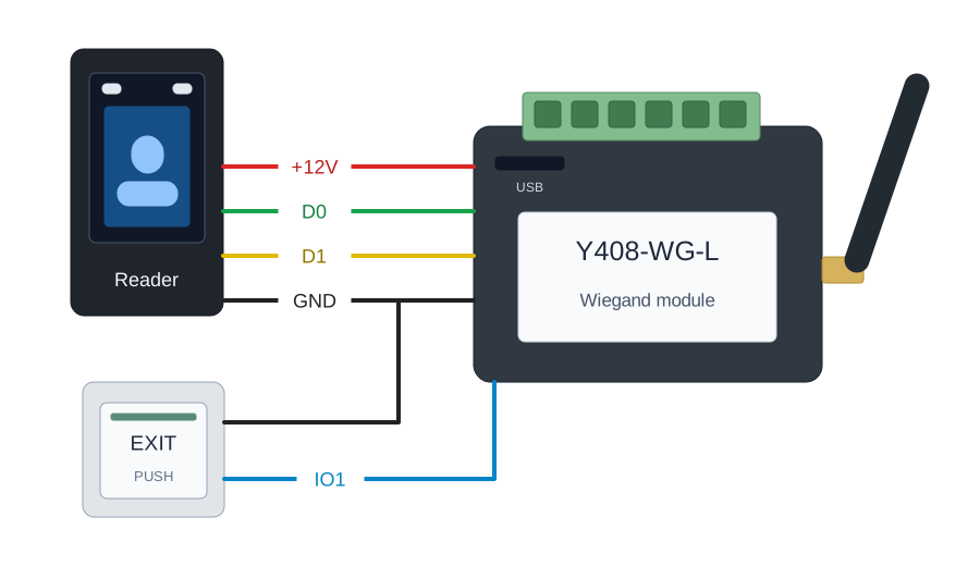
Connect the reader to the first module:
| Reader wire | Module label |
|---|---|
| +12 V | +12V |
| Wiegand D0 | D0 |
| Wiegand D1 | D1 |
| GND | GND |
| BEEP, if required | IO1 |
| LED, if required | IO2 |
This example uses an external 12 V supply shared by the reader and the module, with at least 500 mA output. Size the supply for the combined reader and module current; some readers need more than 500 mA. When sharing a supply, its voltage must suit both devices.
Controller Side
Connect the second module to the controller's Wiegand interface:
| Controller wire | Module label |
|---|---|
| Wiegand power positive | +12V |
| Wiegand D0 | D0 |
| Wiegand D1 | D1 |
| Wiegand GND | GND |
The example uses the controller's Wiegand interface to power this module. Check the available current before using that arrangement. If the controller cannot supply the module, use a suitable external supply and keep the signal reference compatible with the controller.
Wiring Checks
Before powering the modules:
- Check that D0 and D1 are not reversed.
- Verify the reader-side and controller-side grounds are wired as shown by the equipment manuals.
- Check the supply voltage is within 9 to 24 V DC.
- Make sure the antenna is connected.
- Make sure no powered signal is connected to an auxiliary I/O terminal without checking its electrical specification.
Optional Auxiliary I/O Wiring
IO1 and IO2 are optional. The following connections require compatible reader and controller interfaces:
| Use case | Example connection |
|---|---|
| Reader buzzer | Reader BEEP to IO1 |
| Reader LED | Reader LED to IO2 |
| Exit button | Exit-button signal to IO1 |
Check the signal levels, current limits, and input/output behavior at both ends before connecting auxiliary I/O. Test each connected function during commissioning.
Commissioning
Perform the first test on a bench before mounting the antennas at their final positions.
Bench Test
- Connect the reader to module A.
- Connect module B to the controller.
- Power the two modules and the connected equipment.
- Present a valid card, enter a keypad code, or use the connected biometric reader.
- Check that the controller receives the Wiegand event.
- Test the reader's buzzer and LED feedback if IO1 and IO2 are connected.
- Test the exit button if the installation uses the IO1 exit-button arrangement.
Site Test
- Install both antennas in the planned positions.
- Keep rod antennas vertical and away from large metal structures.
- Test valid and invalid credentials at the required operating points.
- Test the door controller's normal feedback.
- Repeat the test with the door closed and with the actual cable routing and enclosure in place.
- Record the verified range and any locations where the link becomes unreliable.
Troubleshooting
| Symptom | Likely cause | Action |
|---|---|---|
| Controller receives no card data | Modules use different channels | Send CONFIG to both modules and set the same channel |
| Controller receives no card data | D0/D1 wiring error | Check D0, D1, and GND at both ends |
| Module does not start | Supply voltage or current is insufficient | Check the 9 to 24 V DC supply and the controller-side power capacity |
| Link works on the bench but fails on site | Obstructions, metal, interference, or poor antenna position | Reposition the antenna, use the external antenna option, and repeat the site test |
| Reader works but feedback does not | IO1/IO2 wiring or logic mismatch | Check the reader feedback wiring and verify the I/O electrical requirements |
| Several nearby links interfere | Channels are too close | Separate channel assignments by 2 to 3 channels where possible |
| USB configuration tool cannot find the module | USB driver, cable, or virtual COM-port issue | Try another cable or port, make sure the virtual serial port appears, and reopen the serial tool |
Firmware Updates
The module supports manufacturer-provided firmware updates through USB. Contact YenGear for the update package and procedure. Custom functions require a separate agreement on scope and availability.
Use only the firmware and update procedure supplied for the specific Y408-WG-L version. Do not disconnect power during an update. Record the current channel configuration before applying a firmware update.
Installation and Safety Notes
- The Y408-WG-L transfers Wiegand signals; it does not replace the access-control controller or lock hardware.
- Keep a local exit and safety-release path where required by the access-control design.
- Do not use this wireless link as the only life-safety or emergency-control path.
- The specified RF band is 433 to 473 MHz. Check the applicable radio requirements for the target country or region before deployment.
- The module is intended for indoor use. Keep it away from rain, condensation, washdown, and other moisture. Check the operating temperature, Wiegand levels, and auxiliary-I/O limits when the project requires those values.
- Validate the final link at the actual installation points. A nominal open-area range does not guarantee the same result inside buildings or around metal structures.
- Manufacturer: Hunan YenGear Tech Co., Ltd.
- Email: [email protected]
- Website: www.yengear.com