
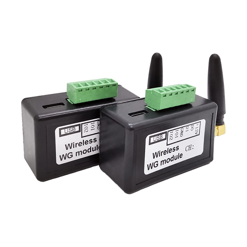
Appearance
Y408-WG-L Point-to-Point Wireless Wiegand Module Specification
| Y408-WG-L |
|---|
 |
Contents
- Overview
- Ordering and Package
- Key Features
- Technical Specifications
- Interfaces and Signals
- Installation and Wiring
- Channel Configuration
- Important Notes
1. Overview
The Y408-WG-L is a point-to-point wireless Wiegand module for extending access-control signals over an RF link. A functional link uses a matched pair: one module connects to a Wiegand card reader, keypad reader, fingerprint reader, or facial-recognition terminal; the other connects to the Wiegand interface on an access-control controller.
The module carries the reader's D0 and D1 signals to the remote controller. It also provides two optional bidirectional I/O channels for compatible reader feedback and exit-button functions. The two modules use the same hardware and are not assigned permanent transmitter or receiver roles. The Y408-WG-L does not replace a door controller, lock power supply, or lock-control system.
Typical Applications
- Access-control reader installation where long Wiegand cables are difficult to route
- Gates, entrances, and remote doors with separated readers and controllers
- Wireless extension of Wiegand readers, fingerprint readers, and facial-recognition terminals
- Retrofit projects that need to preserve an existing Wiegand access-control controller
2. Ordering and Package
Model
| Item | Description |
|---|---|
| Model | Y408-WG-L |
| Product type | Point-to-Point Wireless Wiegand Module |
| Standard product | Matched pair of two modules |
| Required link | Two modules for a complete wireless link |
The standard product is a matched pair of two Y408-WG-L modules. A single module is available only as a replacement option. A complete wireless link requires the pair.
Standard Pair Package
| Qty. | Item |
|---|---|
| 2 | Y408-WG-L modules |
| 2 | 3 dBi rod antennas |
| 1 | USB-C cable |
Check the exact contents when ordering a replacement module or the optional external-antenna version.
3. Key Features
- Wireless Wiegand extension - Replaces a long D0/D1 cable between a reader and an access-control controller.
- Broad Wiegand compatibility - Automatically recognizes WG26 to WG80 formats, including keypad data.
- Automatic endpoint recognition - The modules automatically identify the transmitting and receiving ends after correct wiring.
- Long-range site option - Supplied rod antenna: approximately 500 m unobstructed line of sight. Optional high-gain external antenna: approximately 1,000 m unobstructed line of sight.
- USB-C configuration - The USB-C port exposes a virtual serial port for channel configuration and status queries.
- Channel selection - Configure up to 50 channels through the USB serial interface.
- Auxiliary I/O - Two bidirectional I/O channels support compatible buzzer, LED, and exit-button connections.
- Firmware extension - The USB interface supports manufacturer-provided firmware updates and agreed custom functions.
4. Technical Specifications
Wireless
| Parameter | Specification |
|---|---|
| RF band | 433 to 473 MHz |
| Communication mode | Point-to-point wireless link |
| Configurable channels | 50 channels through the USB serial interface |
| Data transmission delay | Less than 300 ms |
| Supplied antenna | 3 dBi rod antenna |
| Supplied-antenna range | Approximately 500 m unobstructed line of sight |
| Optional antenna | 12 dBi external antenna |
| Optional-antenna range | Approximately 1,000 m unobstructed line of sight |
| Antenna connector | SMA |
Wiegand and I/O
| Parameter | Specification |
|---|---|
| Wiegand format | WG26 to WG80, automatic recognition |
| Keypad data | Supported |
| Wiegand terminal | 3.81 mm pitch, 6-position terminal |
| Auxiliary I/O | 2 bidirectional I/O channels |
| I/O direction | Automatically recognizes input or output |
Electrical and Mechanical
| Parameter | Specification |
|---|---|
| Supply voltage | 9 to 24 V DC |
| Static current | Approximately 50 mA |
| Maximum current | Approximately 300 mA |
| USB interface | USB-C virtual serial port |
| Serial baud rate | Adaptive |
| Dimensions | 61 x 36 x 25 mm |
Check the applicable radio requirements for the target country or region before deployment.
Y408-WG-L is intended for indoor use. Operating temperature, humidity, weight, Wiegand signal-level limits, and auxiliary-I/O electrical limits are not listed in this document. Check these values with YenGear when a project requires them.
5. Interfaces and Signals
Use the labels printed on the module when wiring. The module provides the following signal connections:
| Label | Function |
|---|---|
| +12V | Module power input |
| D0 | Wiegand data line 0 |
| D1 | Wiegand data line 1 |
| GND | Power and signal reference |
| IO1 | Auxiliary bidirectional I/O; used for buzzer or exit-button examples |
| IO2 | Auxiliary bidirectional I/O; used for LED feedback examples |
| USB-C | Virtual serial port for channel configuration and firmware work |
| SMA | Wireless antenna connection |
The exact electrical level and current limits for D0, D1, IO1, and IO2 are not listed in this document. Match the module to the reader and controller documentation before connecting the field wiring.
6. Installation and Wiring
Reader Side

Connect the reader's Wiegand terminals to the Y408-WG-L labels:
| Reader signal | Y408-WG-L |
|---|---|
| Power positive | +12V |
| Wiegand D0 | D0 |
| Wiegand D1 | D1 |
| Power ground | GND |
| Buzzer, if used | IO1 |
| LED feedback, if used | IO2 |
The reader-side installation example uses an external 12 V supply shared by the reader and the module. This example uses a supply with at least 500 mA output. Size the supply for the combined reader and module load.
Controller Side
Connect the second module to the access-control controller's Wiegand interface:
| Controller signal | Y408-WG-L |
|---|---|
| Wiegand power positive | +12V |
| Wiegand D0 | D0 |
| Wiegand D1 | D1 |
| Power ground | GND |
The example uses the controller's Wiegand interface to provide module power. Check the controller's available current before using this arrangement. Use an external supply when the controller cannot provide sufficient capacity.
Antenna
- Tighten the SMA antenna connector before powering the module.
- Install the rod antenna vertically and keep it away from large metal structures.
- Use the optional external antenna when the site requires a longer link or a better antenna position.
- Test the actual link at the planned installation points. Non-line-of-sight obstacles can reduce the range substantially.
7. Channel Configuration
The basic Wiegand data path does not require a Wiegand format setting. The modules automatically recognize the transmitting and receiving ends after correct wiring. Both modules must use the same wireless channel.
The USB-C virtual serial interface provides 50 configurable wireless channels with adaptive baud rate. For setup commands, response examples, and channel verification, see Wireless Channel Configuration in the User Manual.
8. Important Notes
- A complete wireless link requires at least two Y408-WG-L modules.
- The supplied 3 dBi rod antenna provides approximately 500 m unobstructed line of sight. The optional 12 dBi external antenna provides approximately 1,000 m unobstructed line of sight. Actual performance depends on antenna installation, obstructions, metal structures, interference, and site conditions; actual test results prevail.
- The module transfers Wiegand D0/D1 signals. IO1 and IO2 are optional auxiliary I/O; the module does not replace the access-control controller, reader, lock power supply, or lock safety hardware.
- Check the reader and controller documentation for Wiegand signal levels, power capacity, and feedback wiring before installation.
- Keep a local exit and safety-release path where the access-control design requires one. Do not use the wireless link as the only life-safety path.
- Manufacturer-provided firmware updates or custom functions may be available through USB. Function scope and fees require agreement before development.
- Install the module indoors and keep it away from rain, condensation, washdown, and other moisture. Check the electrical limits and regional radio requirements for the target country or region.
- Manufacturer: Hunan YenGear Tech Co., Ltd.
- Address: Room 21014, Building 1, Fudi Xingguang Tiandi, Yingxin Road, Yuhua District, Changsha, Hunan, China
- Email: [email protected]
- Website: www.yengear.com