
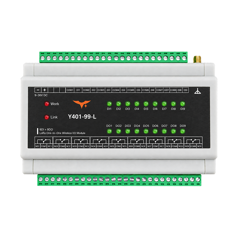
Appearance
Y401-99-L LoRa Wireless I/O Module Specification
Contents
- Overview
- Ordering Information
- Key Features
- Technical Specifications
- Interfaces
- Mechanical and Environmental
- Installation and Wiring
- Important Notes
1. Overview
The Y401-99-L is a nine-channel point-to-point wireless I/O terminal based on LoRa wireless communication. A matched pair contains two bidirectional modules. Each module provides nine digital inputs and nine relay outputs. Each input state is transmitted to the corresponding output channel on the other module.

Operating Logic
- A dry-contact closure or NPN open-collector signal on Device A
DIactivates the correspondingDOrelay on Device B. - When the input returns to its open state, the corresponding remote relay resets.
- Bidirectional operation: the same logic applies from Device B to Device A.
Channel Mapping
| Device A | Device B |
|---|---|
| Channel 1 input | Channel 1 output |
| Channel 2 input | Channel 2 output |
| Channel 3 input | Channel 3 output |
| Channel 4 input | Channel 4 output |
| Channel 5 input | Channel 5 output |
| Channel 6 input | Channel 6 output |
| Channel 7 input | Channel 7 output |
| Channel 8 input | Channel 8 output |
| Channel 9 input | Channel 9 output |
Communication Loss
If wireless communication is lost, the receiver retains the last relay output states for approximately 80 seconds. If communication has not recovered by then, the relay outputs automatically reset to the de-energized (OFF) state. The normally open (NO–COM) contacts open.
2. Ordering Information
Model Configuration
Y401-99-L is a one-to-one LoRa pair. The two digits, 99, specify the digital I/O count on the two sides: each device has 9 DI and 9 DO.
A fast communication version is available with a communication distance of 1000 m and latency below 500 ms. Specify the required version when ordering.
For the full code and examples, see Model Naming.
Matched Pair
A standard pair consists of two matched Y401-99-L modules. Both modules can transmit and receive. The antenna interface uses an SMA female connector; a 470 MHz magnetic-mount antenna is an available antenna option.
3. Key Features
- Nine corresponding input/output signal paths in each direction
- Private point-to-point LoRa communication
- Dry-contact/NPN inputs and relay outputs
- Pluggable field terminals
4. Technical Specifications
Wireless
| Parameter | Specification |
|---|---|
| Communication technology | LoRa wireless communication |
| Standard-version range | Up to 5 km in open areas with clear line of sight |
| Fast-version range | 1000 m |
| Fast-version latency | Less than 500 ms |
| Antenna connector | SMA female connector, external thread and center socket |
| Antenna option | 470 MHz magnetic-mount antenna |
Electrical
| Parameter | Specification |
|---|---|
| Supply voltage | DC 9 to 36 V |
| Max. power consumption | 3 W |
| Input channels | 9 x NPN input / dry-contact switch |
| Input activation | Short the input terminal to COM for a dry-contact input |
| Output channels | 9 x relay output |
| Output rating | AC 250 V 5 A / DC 28 V 5 A |
| Terminal type | 5.08 mm pitch pluggable terminal block |
| Operating temperature | -20 to +85 degC |
| Operating humidity | 10% to 90% RH, non-condensing |
5. Interfaces
| Interface | Description |
|---|---|
| Antenna | SMA female connector for the LoRa antenna |
| Power | DC 9 to 36 V input |
| Input | 9-channel NPN or dry-contact input |
| Output | 9-channel relay output |
| Terminal | 5.08 mm pitch pluggable terminal block |
6. Mechanical and Environmental
| Parameter | Specification |
|---|---|
| Dimensions | 56 x 109 x 160 mm |
| Standard weight | Approx. 910 g |
| Operating temperature | -20 to +85 degC |
| Operating humidity | 10% to 90% RH, non-condensing |
7. Installation and Wiring
Use the Y401 digital I/O user manual for power, input, and relay wiring, paired operation and replacement, and nine-channel commissioning.
Disconnect power before inserting or removing pluggable terminals. Follow the channel and contact markings on the supplied module.
8. Important Notes
- The standard version supports up to 5 km in open areas with clear line of sight. The fast communication version has a communication distance of 1000 m and latency below 500 ms. Actual performance depends on installation, obstructions, interference, and site conditions.
- Never apply voltage directly to a DI terminal.
- Relay ratings are maximum ratings. Select the external contactor, protection, and suppression components for the actual load.
- The wireless link is not intended to be the sole emergency-stop, personnel-safety, or hard-real-time control path.
- Manufacturer: Hunan YenGear Tech Co., Ltd.
- Address: Room 21014, Building 1, Fudi Xingguang Tiandi, Yingxin Road, Yuhua District, Changsha, Hunan, China
- Email: [email protected]
- Website: www.yengear.com