
Appearance
Y301-110/200/020 Serial I/O Modules Specification
| Y301-110 | Y301-200 | Y301-020 |
|---|---|---|
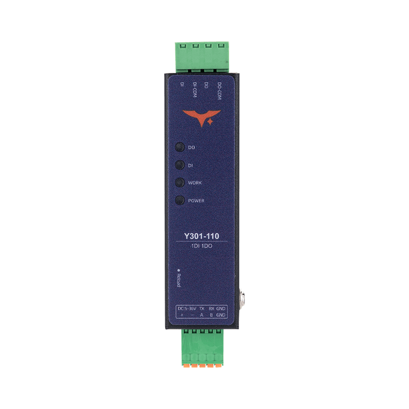 | 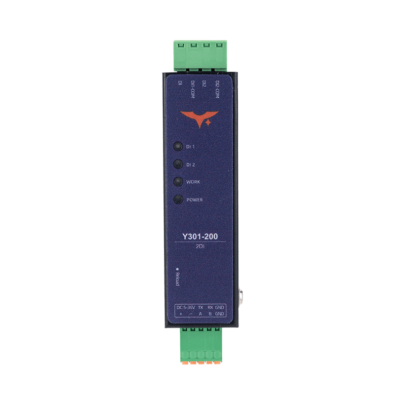 | 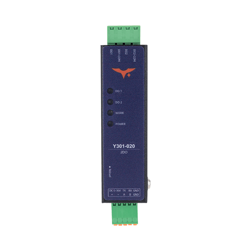 |
Contents
- Overview
- Ordering Information
- Key Features
- Technical Specifications
- Interfaces and Pinout
- Mechanical and Environmental
- Automation Rules
1. Overview
Y301-110/200/020 modules acquire digital inputs and control relay contacts over Modbus RTU. RS485 is standard; RS232 and selected TTL versions are ordering options.
| Model | Digital Input (DI) | Digital Output (DO) | Typical Use Case |
|---|---|---|---|
| Y301-110 | 1 | 1 | Local alarm input and actuator control |
| Y301-200 | 2 | 0 | Dual-channel status monitoring and pulse counting |
| Y301-020 | 0 | 2 | Dual relay control for pumps or valves |
Product Highlights
- Compact DIN-rail or panel-mount form factor for dense control cabinets
- Industrial 5-36 VDC input with reverse-polarity protection
- One or two digital I/O channels for equipment controllers and gateways
2. Ordering Information
2.1 Model Configuration
The I/O code follows DI / DO / AI / AO. These are channel counts on one module; the fourth position is omitted on models without AO.
| Model | DI | DO | AI | AO |
|---|---|---|---|---|
| Y301-110 | 1 | 1 | 0 | 0 |
| Y301-200 | 2 | 0 | 0 | 0 |
| Y301-020 | 0 | 2 | 0 | 0 |
For the full code and examples, see Model Naming.
2.2 Interface Options
Specify the required interface when ordering:
| Interface | Description |
|---|---|
| RS485 | Standard version for Modbus RTU multi-drop networks |
| RS232 | Optional version for point-to-point communication |
| TTL | Optional on selected models for direct MCU integration |
2.3 Ordering Table
| SKU | Description |
|---|---|
| Y301-110 | 1 DI + 1 DO, Modbus RTU |
| Y301-200 | 2 DI, input-only module |
| Y301-020 | 2 DO, output-only module |
3. Key Features
- Enclosure - 77.4 × 22.5 × 16.2 mm for space-constrained installations
- Flexible configuration - Three model variants cover common digital I/O requirements
- Modbus RTU ready - RS485/RS232/TTL interface options simplify system integration
- Power and operating environment - 5-36 VDC input and -40 to +85 °C operating range
- Opto-isolated inputs - Supports both dry contact and wet contact signals
- Relay outputs - Rated up to 125 VAC / 0.5 A or 30 VDC / 2 A
- Pulse counting - Selectable rising/falling edge and configurable debounce on DI models; Y301-200 retains accumulated counts after power loss
- Built-in automation - Local rules on models with DO channels
4. Technical Specifications
4.1 Electrical and Environmental
| Parameter | Specification |
|---|---|
| Supply voltage | 5-36 VDC |
| Operating temperature | -40 to +85 °C |
| Humidity | 5-95% RH |
4.2 Digital Input
| Item | Specification |
|---|---|
| Channel count | 1 (Y301-110) or 2 (Y301-200) |
| Type | Dry/wet contact, opto-isolated |
| Sampling rate | 100 Hz |
| Pulse counter | 32-bit unsigned accumulated count, selectable rising/falling edge |
| Counter retention | Y301-200: accumulated counts are retained after power loss |
| Debounce | 5-255 ms (default 50 ms) |
The sampling rate is not a guaranteed maximum pulse frequency. Select debounce to suit the contact bounce and pulse timing: after a counting edge is detected, signals within the debounce interval are not counted.
Pulse Counter Registers
Read each counter with Modbus function code 0x03, requesting two consecutive 16-bit holding registers. Values use big-endian order (high word first). Writing 0 clears the counter; other write values are not allowed.
| Channel | Modbus Addresses | PLC Addresses | Models |
|---|---|---|---|
| DI1 | 0x0500-0x0501 | 41281-41282 | Y301-110, Y301-200 |
| DI2 | 0x0502-0x0503 | 41283-41284 | Y301-200 |
| Setting | Modbus Address | Values |
|---|---|---|
| Counting edge | 0x0041 | 0 = falling edge; 1 = rising edge |
| Debounce time | 0x0042 | 5-255 ms; default 50 ms |
Read or explicitly set the counting edge during commissioning to match the application.
4.3 Digital Output
| Item | Specification |
|---|---|
| Channel count | 1 (Y301-110) or 2 (Y301-020) |
| Type | SPDT relay |
| Contact rating | 125 VAC 0.5 A / 30 VDC 2 A |
| Electrical life | 100,000 cycles |
4.4 Communication
| Item | Specification |
|---|---|
| Interface | RS485 (2-wire), optional RS232 or TTL |
| Protocol | Modbus RTU slave |
| Baud rate | 600-230400 bps (default 9600) |
| Slave address | 1-255 (software configurable; default 1) |
| Data bits | 8 or 9 (default 8) |
| Stop bits | 1 or 2 (default 1) |
| Parity | None, odd or even (default none) |
5. Interfaces and Pinout
5.1 Terminal Overview
| Group | Y301-110 | Y301-200 | Y301-020 |
|---|---|---|---|
| Power | +, - (5-36 VDC) | +, - (5-36 VDC) | +, - (5-36 VDC) |
| Reload | Hold 3-15 s to restore factory defaults | Hold 3-15 s to restore factory defaults | Hold 3-15 s to restore factory defaults |
| DI | DI, DI-COM | DI1, DI1-COM, DI2, DI2-COM | None |
| DO | NC1 / COM1 / NO1 | None | NC1/NC2 / COM1/COM2 / NO1/NO2 |
| Communication | A/B/GND (RS485) or TX/RX/GND (RS232/TTL) | A/B/GND (RS485) or TX/RX/GND (RS232/TTL) | A/B/GND (RS485) or TX/RX/GND (RS232/TTL) |
5.2 Wiring Guidelines
- Power off before wiring.
- For Y301-200 dry-contact input, connect
DI1-COMto the supply negative and connect the supply positive toDI1through the external contact. Wire DI2 in the same way usingDI2-COMandDI2. - For wet-contact input, connect the signal positive to the selected
DIand the signal negative to itsDI-COM. Confirm the permitted input voltage for the supplied hardware before connection. - Use the terminal markings and wiring diagram for the supplied model; larger models in the series use different DI common-terminal arrangements.
- For relay outputs driving inductive loads, add an RC snubber for AC loads or a flyback diode for DC loads.
- For RS485, use shielded twisted pair, appropriate end termination, and a common reference ground.
6. Mechanical and Environmental
| Item | Value |
|---|---|
| Dimensions | 77.4 x 22.5 x 16.2 mm |
| Mounting | DIN rail or screw mounting |
7. Automation Rules
Automation rules apply to Y301-110 and Y301-020. Y301-200 has no DO channels.
| Mode | Description |
|---|---|
| DI follow | DO mirrors the DI state |
| Pulse output | Configurable ON/OFF pulse width |
| Delay control | Programmable ON/OFF delay |
| Cyclic toggle | Periodic ON/OFF cycling |
| Timer/schedule | Time-based activation |
| Logic mode | AND/OR/XOR logic combination |
| Delayed follow | DO follows DI after a configured delay |
| Button mode | Configurable action triggered by DI |
- Two rules per DO channel: 2 rules on Y301-110 and 4 rules on Y301-020
- Rules run locally without host polling
- DO output-state retention is not supported on these compact models. This is separate from Y301-200 pulse-counter retention.
- Manufacturer: Hunan YenGear Tech Co., Ltd.
- Address: Room 21014, Building 1, Fudi Xingguang Tiandi, Yingxin Road, Yuhua District, Changsha, Hunan, China
- Email: [email protected]
- Website: www.yengear.com