
Appearance
Y402-11-L LoRa One-to-Many Wireless I/O Module System Specification
| Y402-11-L Master | Y402-11-L Slave |
|---|---|
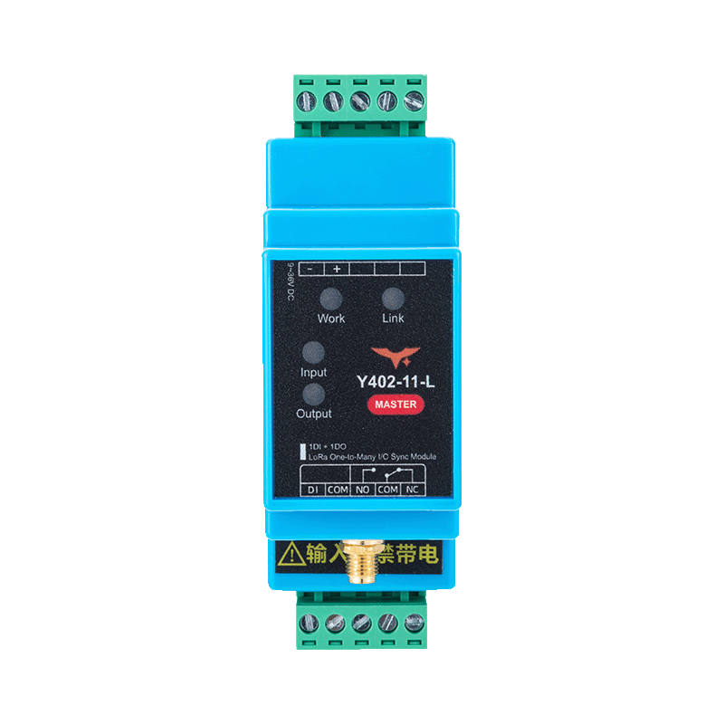 | 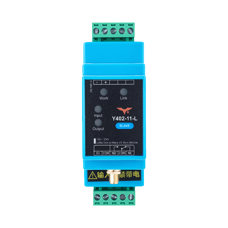 |
Contents
- Overview
- Ordering Information
- Key Features
- Technical Specifications
- Interfaces and Indicators
- Mechanical and Environmental
- Installation and Wiring
- Important Notes
1. Overview
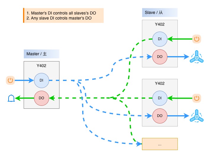
Y402-11-L links one master with one or more slaves over LoRa. Each unit has 1 DI and 1 SPDT relay output. The basic master/slave set is factory paired.
Operating Logic
- Master to slave: when the master
DIis closed, theDOon all slave units energizes - Slave to master: when the
DIon any slave is closed, theDOon the master energizes - During normal communication, the master output resets only after the
DIon all slave units returns to open
Communication Loss
If wireless communication is lost, the receiver retains the last relay output states for approximately 80 seconds. If communication has not recovered by then, the relay outputs automatically reset to the de-energized (OFF) state. The normally open (NO–COM) contacts open.
2. Ordering Information
System Components
| Device | Model | Role |
|---|---|---|
| Master | Y402-11-L | Central control unit |
| Slave | Y402-11-L | Remote terminal unit |
System configuration:
- Basic system: 1 master + 1 slave (factory paired)
- Expanded system: 1 master + N slaves
Model Configuration
Y402-11-L is a one-to-many LoRa system. The first digit, 1, specifies 1 DI and 1 DO on the master; the second digit, 1, specifies 1 DI and 1 DO on each slave.
For the full code and examples, see Model Naming.
Package Contents
| Qty. | Item |
|---|---|
| 1 | Y402-11-L master module |
| 1 | Y402-11-L slave module |
| 2 | 470 MHz magnetic-mount antennas |
| 2 | DIN rail clips |
| 1 | Quick reference guide |
| 1 | Warranty card |
3. Key Features
- Passive dry-contact/NPN inputs and SPDT relay outputs
- Reverse-polarity protection
- Hardware watchdog
- Private LoRa communication without a SIM card or Internet gateway
4. Technical Specifications
Wireless
| Parameter | Specification |
|---|---|
| Frequency band | 398 to 525 MHz |
| Communication mode | Half-duplex |
| Communication range | Up to 5 km standard; 10 km option available for selected configurations |
| Antenna connector | SMA |
| Standard antenna | 470 MHz magnetic-mount antenna |
Electrical
| Parameter | Specification |
|---|---|
| Supply voltage | 9 to 36V DC |
| Max. power consumption | 1W (master) / 0.8W (slave) |
| Input type | Passive dry contact / NPN open-collector (no voltage input to DI) |
| Output type | SPDT relay |
| Output rating | AC 277V 5A / DC 28V 5A |
| Operating temperature | -20 to +85 degC |
| Operating humidity | 10% to 90% RH, non-condensing |
5. Interfaces and Indicators
Interface Summary (Master and Slave)
| Interface | Description |
|---|---|
| Antenna | SMA connector for LoRa antenna |
| Power | DC 9 to 36V input with reverse-polarity protection |
| Input | Passive switch input (DI + COM) |
| Output | Relay output (NO + COM + NC) |
LED Indicators
| LED | Function | Status |
|---|---|---|
| Work | System status | On after power-up |
| Link | Link status | On when the wireless link is established |
| Input | Input status | On when DI is closed |
| Output | Output status | On when the relay is energized |
6. Mechanical and Environmental
Mechanical Specifications
| Parameter | Master | Slave |
|---|---|---|
| Dimensions | 88 x 72 x 59 mm | 88 x 37 x 59 mm |
| Weight | Approx. 50 g | Approx. 50 g |
| Mounting | 35 mm DIN rail | 35 mm DIN rail |
| Protection rating | IP20 | IP20 |
| Housing material | Flame-retardant plastic | Flame-retardant plastic |
7. Installation and Wiring
Use the Y402-11-L user manual for power, input, and relay wiring, pairing or replacement, and commissioning.
DI accepts dry contacts or NPN open-collector signals, not voltage inputs. Relay contacts require an external load supply. Select the load and protection against the electrical ratings above.
8. Important Notes
- Range figures assume an open-area installation. The 10 km option requires the specified configuration and antenna; obstructions, interference, and antenna placement affect the installed link.
- The half-duplex wireless link is unsuitable for guaranteed timing or as the sole emergency-stop/personnel-safety path.
- Use one master per system.
- Manufacturer: Hunan YenGear Tech Co., Ltd.
- Address: Room 21014, Building 1, Fudi Xingguang Tiandi, Yingxin Road, Yuhua District, Changsha, Hunan, China
- Email: [email protected]
- Website: www.yengear.com