
Appearance
Wireless I/O Module (Y401 / Y402 / Y403 / Y406 / Y401WG-L / Y412)
The YenGear wireless signal family covers three related product groups. Y401, Y402, Y403, and Y412 extend digital control and analog measurement signals over a private LoRa link. Y406 adds handheld LoRa control and RS485 communication for relay-controlled equipment. Y401WG-L extends Wiegand access-control signals over a separate point-to-point RF link.
The Y401, Y402, and Y403 families cover point-to-point, one-to-many, and Auto Relay relationships; Y412 adds configurable 2-, 4-, and 8-channel master/slave control. Y401WG-L carries WG26 to WG80 data between an access-control reader and controller and provides optional auxiliary bidirectional I/O channels. No SIM card, Internet connection, or LoRaWAN gateway is required for the Y401/Y402/Y403/Y412 links. Actual range depends on antenna installation, obstructions, interference, and site conditions.
For model-code rules, topology comparison, and model selection, use the Y401 / Y402 / Y403 Selection Guide. This page provides the family overview, model directory, and document entry points.
Model Directory
Digital I/O Models
| Product image | Model | DI | DO | Control relationship | Documents |
|---|---|---|---|---|---|
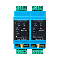 | Y401-11-L | 1 | 1 | Point-to-point (A ↔ B) | Manual · Specification |
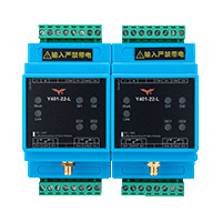 | Y401-22-L | 2 | 2 | Point-to-point (A ↔ B) | Manual · Specification |
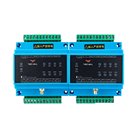 | Y401-44-L | 4 | 4 | Point-to-point (A ↔ B) | Manual · Specification |
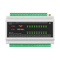 | Y401-99-L | 9 | 9 | Point-to-point (A ↔ B) | Manual · Specification |
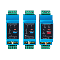 | Y402-11-L | 1 | 1 | One-to-many (master ↔ slaves) | Manual · Specification |
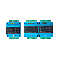 | Y402-44-L | 4 | 4 | One-to-many (master ↔ slaves) | Manual · Specification |
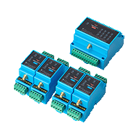 | Y402-41-L | 4 master / 1 slave | 4 master / 1 slave | One-to-many, 4-to-1 mapping | Manual · Specification |
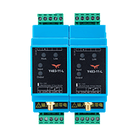 | Y403-11-L | 1 per node | 1 per node | Auto Relay | Manual · Specification |
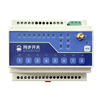 | Y412-22/44/88-L | 2 / 4 / 8 | 2 / 4 / 8 | Configurable master/slave; unidirectional or bidirectional | Manual · Specification |
Handheld LoRa Controllers
Y406 provides handheld LoRa control in 2-, 4-, 6-, 8-, and 16-circuit models with a 9–72 V DC supply. PLC expansion-board firmware provides Modbus RTU key-state reads over RS485; relay-controller commands depend on the supplied firmware.
| Product image | Series / accessory | Selection | Documents |
|---|---|---|---|
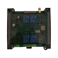 | Y406-22/44/66/88/GG-L | 2 / 4 / 6 / 8 / 16 circuits; 9–72 V DC | Specification · User Manual |
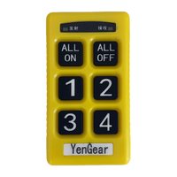 | Y406T-44-L | Handheld remote shown with Y406-44-L; select the key layout when ordering | Controller Specification |
Wiegand Signal Extension
Y401WG-L is a point-to-point wireless Wiegand module rather than a LoRa I/O module. Use the standard matched pair of two modules to carry access-control reader data to a remote controller.
| Product image | Model | Signal path | Wireless link | Range planning value | Documents |
|---|---|---|---|---|---|
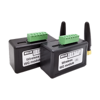 | Y401WG-L | WG26 to WG80 + optional auxiliary I/O | Point-to-point RF, 433 to 473 MHz | Approx. 500 m line of sight in an open area with the supplied rod antenna; approximately 1,000 m line of sight in an open area with the optional external antenna | Specification · User Manual |
Analog I/O Models
Both analog models use a point-to-point link and have no DI or DO channels. Channel counts below are per module.
| Product image | Model | AI | AO | Signal type | Supply | Documents |
|---|---|---|---|---|---|---|
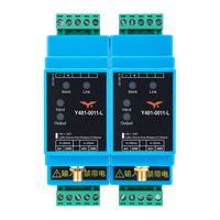 | Y401-0011-L | 1 | 1 | 4-20 mA | 9-36 V DC | Manual · Specification and wiring diagrams |
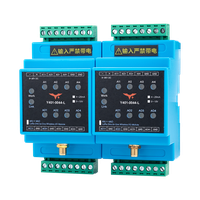 | Y401-0044-L | 4 | 4 | 4-20 mA or 0-10 V | 9-36 V DC | Manual · Specification and wiring diagrams |
Both analog models have no digital I/O on either side: Y401-0011-L has 1 AI and 1 AO per device, and Y401-0044-L has 4 AI and 4 AO per device. Select the required analog signal option when ordering and use the supplied model configuration for wiring.
Each specification includes two-, three-, and four-wire current connection examples. The Y401-0044-L specification also describes 0-10 V wiring; the two-wire current-loop example applies only to 4-20 mA.
Y412 — Configurable Wireless I/O Module
Y412 is the configurable multi-channel member of the Wireless I/O Module family. Choose 2DI + 2DO, 4DI + 4DO, or 8DI + 8DO hardware, then set the master/slave role and control mode for the site. Bidirectional follow and unidirectional feedback modes support remote start/stop, valve and pump control, lighting groups, and other auxiliary relay applications.
| Selection point | Y412 options |
|---|---|
| Channel count | 2, 4, or 8 DI + DO per module |
| Control mode | Master/slave; unidirectional feedback or bidirectional follow |
| Output action | Momentary or latching |
| Power versions | 8–28 VDC or 85–265 VAC |
| Relay output | Form A, up to 5 A at 250 VAC or 30 VDC |
| Range planning | Up to 5 km standard; 10 km option available for selected configurations* |
See the Y412 Specification and Y412 User Manual for wiring, DIP settings, and commissioning.
Related Field-Ready Products
For a complete enclosure, power system, and field interface built around the wireless link, see the Y901 Integrated Multi-Point Wireless Alarm System and Y953 Wireless Control Cabinet. These are complete products, not additional Wireless I/O Module SKUs.
Document Map
Use the Y401 / Y402 / Y403 Selection Guide for model naming, topology comparison, and selection. For wiring, pairing, and commissioning, use the manuals linked in the model directory. Use each model specification for exact I/O, power, range, relay, analog-signal, and environmental limits.
For Y406 installation, remote operation, RS485 / Modbus RTU PLC communication, and troubleshooting, see the Y406 Specification and Y406-22/44/66/88/GG-L User Manual.
For Y412 wiring and commissioning, see the Y412 User Manual.
For analog installation and commissioning, use the Y401 Analog I/O User Manual. For model-specific limits, use the Y401-0011-L and Y401-0044-L specifications.
For Y401WG-L Wiegand wiring, channel configuration, commissioning, and troubleshooting, see the Y401WG-L Specification and Y401WG-L User Manual.
- Manufacturer: Hunan YenGear Tech Co., Ltd.
- Email: [email protected]
- Website: www.yengear.com