
Appearance
Y412 Wireless I/O Module User Manual
Applicable models:
Y412-22-L,Y412-44-L,Y412-88-L
Contents
- Before You Start
- 3-Minute Quick Start
- DIP Switches and Modes
- Typical Wiring
- Recommended Setup by Scenario
- Troubleshooting
1. Before You Start
The Y412 is designed for fast deployment with minimal setup. In most projects, you only need to complete four steps:
- Confirm the model and channel count (
22,44, or88). - Connect power and antenna.
- Set the channel (DIP switches 1 to 5, identical within the same communication group).
- Set the operating mode (momentary / latching + unidirectional / bidirectional + master / slave).
2. 3-Minute Quick Start
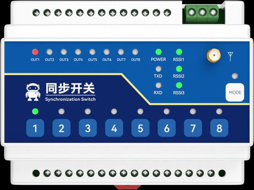
Step 1: Power On and Basic Check
- The
POWERLED should stay on. - Any lit
RSSILED indicates that a wireless link has been established. - The red
OUTLEDs show the output status of each channel.
Step 2: Keep the Channel Setting the Same
- DIP switches 1 to 5 must match on Device A and Device B.
- It is recommended to validate the default channel first, then change it if required by the site.
Step 3: Select the Operating Mode
- First decide the master/slave role: only one master is allowed in each network.
- Then decide the control direction: unidirectional feedback or bidirectional follow.
- Finally decide the output action: momentary or latching.
Step 4: Verify with Local Push-Buttons
- Press a local key on one device and check whether the corresponding
OUTLED changes on the remote device. - Validate one channel first, then test the remaining channels.
3. DIP Switches and Modes
3.1 DIP Switch Definition
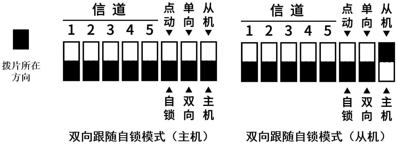
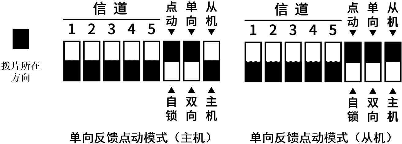
1 to 5: channel setting (32 channels total)6: momentary / latching7: unidirectional / bidirectional8: slave / master
3.2 Typical Mode Examples
3.3 Mode Description
- Bidirectional follow: both master and slave can trigger the remote output.
- Unidirectional feedback: the master typically drives the slave, while the slave returns output status feedback.
- Latching: each short press toggles the output state on or off.
- Momentary: the output stays on only while the input is active.
4. Typical Wiring
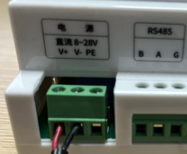
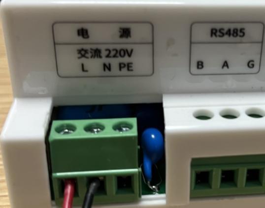
4.1 Power Wiring
- DC version:
V+ / V- / PE - AC version:
L / N / PE
4.2 Digital Input Wiring
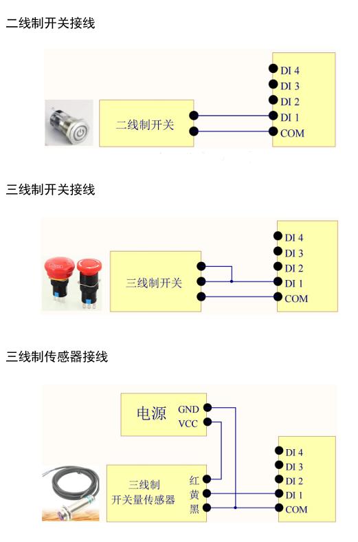
Supports 2-wire switches, 3-wire switches, and 3-wire sensors.
5. Recommended Setup by Scenario
Scenario A: Remote Start/Stop Control
- Mode:
Unidirectional + Latching - Use case: pumps, fans, and lighting circuits
- Benefit: local push-button action and remote output state remain easy to understand
Scenario B: Press-and-Hold Operation
- Mode:
Unidirectional + Momentary - Use case: loads that should operate only while the button is pressed
- Benefit: reduces the risk of unintended maintained output
Scenario C: Two-Way Mutual Control
- Mode:
Bidirectional + Latching - Use case: controlling the same type of equipment from two separate locations
- Benefit: both ends can operate as a control point
6. Troubleshooting
1. Devices Do Not Link
- Check whether DIP switches 1 to 5 are exactly the same.
- Check whether there is only one master in the network.
- Check whether the antenna is tightened and whether any
RSSILED is on.
2. Input Changes but Output Does Not Switch
- Check whether the device is in momentary or latching mode.
- Check whether the load is wired correctly to
DO COMandDO NO. - Check whether the channel indicator LED turns on.
3. The System Works but Disconnects Occasionally
- Increase antenna height and reduce obstacles.
- Switch to a range-priority configuration.
- Enable timeout reset through the host-side configuration tool if needed.
4. More Advanced Settings Are Required
- Use the configuration tool through RS485 or serial communication to read and write parameters.
- Manufacturer: Hunan YenGear Tech Co., Ltd.
- Email: [email protected]
- Website: www.yengear.com