
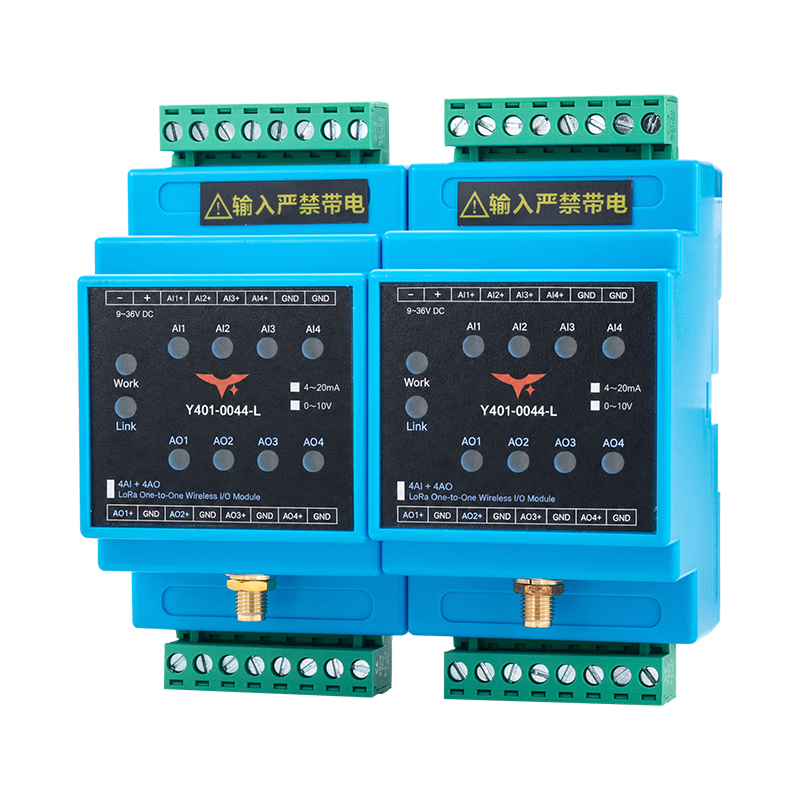
Appearance
Y401-0044-L LoRa Wireless Analog I/O Synchronization Module Specification
Contents
- Overview
- Ordering Information
- Key Features
- Technical Specifications
- Interfaces and Indicators
- Mechanical and Environmental
- Installation and Wiring
- Important Notes
1. Overview
The Y401-0044-L is a four-channel point-to-point wireless analog I/O synchronization module using LoRa communication. Each module provides four analog inputs and four analog outputs. Order the module with either a 4-20 mA current signal configuration or a 0-10 V voltage signal configuration.
A link uses two modules. Analog inputs at one module are transmitted wirelessly to the corresponding outputs at the other module. On the 4-20 mA version, the four channels operate independently over a half-duplex link. The pair is matched at the factory and needs no on-site configuration for normal operation. The signal configuration, accuracy, and loading limits must match the ordered version.
Signal Mapping
| Channel | Device A to Device B | Device B to Device A |
|---|---|---|
| 1 | AI1 → AO1 | AI1 → AO1 |
| 2 | AI2 → AO2 | AI2 → AO2 |
| 3 | AI3 → AO3 | AI3 → AO3 |
| 4 | AI4 → AO4 | AI4 → AO4 |
Use matching signal types at the source, module input, remote output, and receiving instrument. Select one signal configuration for the module pair and use matching field instruments.
2. Ordering Information
Model Configuration
Y401-0044-L is a one-to-one LoRa analog pair. The first two digits, 00, indicate no digital I/O on either side; the final two digits, 44, indicate 4 AI and 4 AO on each device.
For the full code and examples, see Model Naming.
Signal Options
| Signal type | Nominal range |
|---|---|
| Current | 4-20 mA |
| Voltage | 0-10 V |
Specify the required signal type when ordering. The faceplate has separate marks for the two ranges. Use the supplied signal configuration and do not connect a different signal type.
3. Key Features
- Four matching analog signal paths in each direction
- Current or voltage configuration selected when ordering
- Active constant-current outputs on the 4–20 mA version
- Individual channel indicators and labeled output/return terminal pairs
4. Technical Specifications
| Parameter | Specification |
|---|---|
| Model | Y401-0044-L |
| Wireless technology | LoRa |
| Network topology | Point-to-point |
| Communication mode, 4-20 mA version | Half-duplex |
| Frequency band, 4-20 mA version | 398 to 525 MHz |
| Antenna, 4-20 mA version | SMA connector; 470 MHz magnetic-mount antenna |
| Communication range | Up to 5 km standard; 10 km option available for selected configurations |
| Analog inputs | 4 |
| Analog outputs | 4 |
| Analog signal options | 4-20 mA or 0-10 V |
| Digital I/O | None |
| Input terminals | AI1+, AI2+, AI3+, AI4+, GND, GND |
| Output terminals | AO1+/GND, AO2+/GND, AO3+/GND, AO4+/GND |
| Field terminals | 5.08 mm pitch pluggable terminals |
| Indicators | Work, Link, AI1-AI4, AO1-AO4 |
Signal-Version Electrical Specifications
| Parameter | 4-20 mA version | 0-10 V version |
|---|---|---|
| Supply voltage | 9-36 V DC | 9-36 V DC |
| Max. power consumption | Approx. 2 W | 1.5 W |
| Analog input | 4 x active 4-20 mA current inputs | 4 x 0-10 V voltage inputs |
| Input accuracy | ≤ ±0.3 mA acquisition accuracy | ≤ ±0.1 V acquisition accuracy |
| Input source or limit | Active signal; current-source voltage ≥10 V; Imax ≤24 mA | Maximum input voltage Vmax ≤10 V |
| Analog output | 4 x active 4-20 mA constant-current outputs | 4 x 0-10 V voltage outputs |
| Output accuracy or error | ≤ ±0.3 mA output error; load ≤500 ohms | ≤ ±0.1 V output accuracy |
| Operating temperature | -20 to +75 °C | -20 to +75 °C |
Both versions use 9-36 V DC power. Do not apply current-version signal or load limits to a voltage-configured module.
5. Interfaces and Indicators
Terminal Layout
The following order follows the faceplate viewed from the front, left to right. The positions below identify locations in each row, not printed terminal numbers.
| Row position | Upper row | Lower row |
|---|---|---|
| 1 | −: DC supply negative | AO1+: channel 1 output |
| 2 | +: DC supply positive | GND: output return |
| 3 | AI1+: channel 1 input | AO2+: channel 2 output |
| 4 | AI2+: channel 2 input | GND: output return |
| 5 | AI3+: channel 3 input | AO3+: channel 3 output |
| 6 | AI4+: channel 4 input | GND: output return |
| 7 | GND: input return | AO4+: channel 4 output |
| 8 | GND: input return | GND: output return |
Connect each output circuit to its labeled AO terminal and adjacent GND. The GND markings do not establish galvanic isolation between channels or between signal and power circuits.
Indicators
The following status descriptions apply to the 4-20 mA version.
| Label | Function | Status |
|---|---|---|
| Work | Module operation | On after startup |
| Link | Wireless link | On when the paired module is connected; off when disconnected; flashing indicates abnormal communication |
| AI1-AI4 | Corresponding analog input channel | On when input current is detected; off when no current is detected |
| AO1-AO4 | Corresponding analog output channel | On while output current is produced; off when no current is produced |
6. Mechanical and Environmental
Mechanical Specifications — 4-20 mA Version
| Parameter | Specification |
|---|---|
| Overall dimensions, W × H × D | 54 × 112 × 59 mm, as shown in the enclosure drawing |
| Weight | Approx. 350 g |
| Mounting | 35 mm DIN rail |
Use the supplied enclosure drawing for the 0-10 V version and for mounting clearances.
Environmental Specifications — 4-20 mA Version
| Parameter | Specification |
|---|---|
| Operating temperature | -20 to +75 °C |
| Operating humidity | 10% to 90% RH, non-condensing |
7. Installation and Wiring
Use the user manual for 4–20 mA input wiring, two-wire AO connections, 0–10 V wiring, and commissioning.
The four inputs share the input GND terminals. Each output uses its labeled AO+ and adjacent GND. Module and field-instrument power connections are separate from the signal pairs.
8. Important Notes
- Range figures assume an open-area installation. The 10 km option requires the specified configuration and antenna; obstructions, interference, and antenna placement affect the installed link.
- Use the ordered current or voltage configuration throughout the signal path. Do not apply a voltage signal to a current-configured input.
- Current-version load limits do not define voltage-output drive limits. Check the voltage output's minimum load resistance against the receiver input impedance before connection.
- The 4–20 mA version uses half-duplex communication with variable delay. Assess timing and output behavior during link loss and recovery before connecting a control load.
- Do not use the wireless link as the sole emergency-stop or personnel-safety path.
- Manufacturer: Hunan YenGear Tech Co., Ltd.
- Email: [email protected]
- Website: www.yengear.com