
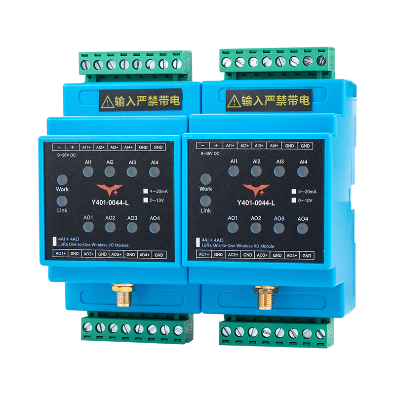
Appearance
Y401-0044-L LoRa Wireless Analog I/O Synchronization Module Datasheet
Contents
- Overview
- Ordering Information
- Key Features
- Technical Specifications
- Interfaces and Indicators
- Mechanical and Environmental
- Installation and Wiring
- Important Notes
1. Overview
The Y401-0044-L is a four-channel point-to-point wireless analog I/O synchronization module using LoRa communication. Each module provides four analog inputs and four analog outputs. Order the module with either a 4-20 mA current signal configuration or a 0-10 V voltage signal configuration.
A link uses two modules. Analog inputs at one module are transmitted wirelessly to the corresponding outputs at the other module. The diagrams in this document illustrate one channel in the Device A-to-Device B direction. The signal configuration, supply range, accuracy, and loading limits must match the ordered version.
The standard open-area planning range is up to 5 km. A 10 km range option is available for selected configurations with the specified antenna and installation conditions.
Signal Mapping
| Channel | Device A to Device B | Device B to Device A |
|---|---|---|
| 1 | AI1 → AO1 | AI1 → AO1 |
| 2 | AI2 → AO2 | AI2 → AO2 |
| 3 | AI3 → AO3 | AI3 → AO3 |
| 4 | AI4 → AO4 | AI4 → AO4 |
Use matching signal types at the source, module input, remote output, and receiving instrument. Current-to-voltage conversion and mixed signal types across channels are not specified.
Typical Applications
- Wireless extension of analog process signals
- Remote pressure, level, flow, and temperature monitoring
- Analog signal transfer between field instruments and control panels
2. Ordering Information
Model Configuration
Y401-0044-L is a one-to-one LoRa analog pair. The first two digits, 00, indicate no digital I/O on either side; the final two digits, 44, indicate 4 AI and 4 AO on each device.
For the full code and examples, see Model Naming.
Signal Options
| Signal type | Nominal range |
|---|---|
| Current | 4-20 mA |
| Voltage | 0-10 V |
Specify the required signal type when ordering. The faceplate has separate marks for the two ranges. Use the supplied signal configuration and do not connect a different signal type.
3. Key Features
- Four analog inputs and four analog outputs per module
- 4-20 mA or 0-10 V signal options with version-specific electrical limits
- Point-to-point LoRa wireless communication
- Version-specific supply: 9-36 V DC for the 4-20 mA version and 12-36 V DC for the 0-10 V version
- Version-specific power consumption: approximately 2 W for the 4-20 mA version and 1.5 W for the 0-10 V version
- Work and Link indicators, plus individual AI1-AI4 and AO1-AO4 indicators
- Labeled input channels and separate output terminal pairs
4. Technical Specifications
| Parameter | Specification |
|---|---|
| Model | Y401-0044-L |
| Wireless technology | LoRa |
| Network topology | Point-to-point |
| Communication range | Up to 5 km standard; 10 km option available for selected configurations |
| Analog inputs | 4 |
| Analog outputs | 4 |
| Analog signal options | 4-20 mA or 0-10 V |
| Digital I/O | None |
| Input terminals | AI1+, AI2+, AI3+, AI4+, GND, GND |
| Output terminals | AO1+/GND, AO2+/GND, AO3+/GND, AO4+/GND |
| Field terminals | 5.08 mm pitch pluggable terminals |
| Indicators | Work, Link, AI1-AI4, AO1-AO4 |
Signal-Version Electrical Specifications
| Parameter | 4-20 mA version | 0-10 V version |
|---|---|---|
| Supply voltage | 9-36 V DC | 12-36 V DC |
| Max. power consumption | Approx. 2 W | 1.5 W |
| Analog input | 4 x active 4-20 mA current inputs | 4 x 0-10 V voltage inputs |
| Input accuracy | ≤ ±0.3 mA acquisition accuracy | ≤ ±0.1 V acquisition accuracy |
| Input source or limit | Active signal; current-source voltage ≥10 V; Imax ≤24 mA | Maximum input voltage Vmax ≤10 V |
| Analog output | 4 x active 4-20 mA constant-current outputs | 4 x 0-10 V voltage outputs |
| Output accuracy or error | ≤ ±0.3 mA output error; load ≤500 ohms | ≤ ±0.1 V output accuracy |
| Operating temperature | -20 to +75 °C | -20 to +75 °C |
| Operating humidity | 10% to 90% RH, non-condensing | Not stated in the supplied voltage-version figure |
The 4-20 mA values in this table follow the Y401-0011-L core electrical and environmental parameters, excluding dimensions. The 0-10 V values follow the supplied voltage-version figure. Do not apply the current-version input, output, supply, or load limits to a voltage-configured module.
This datasheet defines the supported I/O, signal options, terminal layout, and wiring. Use the supplied model configuration and order confirmation for resolution, input impedance, output drive, radio frequency, update timing, dimensions, and other values not listed here.
5. Interfaces and Indicators
Terminal Layout
The following order follows the faceplate viewed from the front, left to right. The positions below identify locations in each row, not printed terminal numbers.
| Row position | Upper row | Lower row |
|---|---|---|
| 1 | −: DC supply negative | AO1+: channel 1 output |
| 2 | +: DC supply positive | GND: output return |
| 3 | AI1+: channel 1 input | AO2+: channel 2 output |
| 4 | AI2+: channel 2 input | GND: output return |
| 5 | AI3+: channel 3 input | AO3+: channel 3 output |
| 6 | AI4+: channel 4 input | GND: output return |
| 7 | GND: input return | AO4+: channel 4 output |
| 8 | GND: input return | GND: output return |
Connect each output circuit to its labeled AO terminal and adjacent GND. The GND markings do not establish galvanic isolation between channels or between signal and power circuits.
Indicators
| Label | Indicated function |
|---|---|
| Work | Module operation |
| Link | Wireless link |
| AI1-AI4 | Corresponding analog input channel |
| AO1-AO4 | Corresponding analog output channel |
The faceplate identifies these indicators but does not define their on, off, or flashing behavior.
6. Mechanical and Environmental
Use the model enclosure drawing supplied with the order for panel and mounting dimensions. Do not infer enclosure dimensions or environmental ratings from faceplate artwork.
7. Installation and Wiring
Power Wiring
Connect a regulated DC supply to the upper-row + and − terminals. Use 9-36 V DC for the 4-20 mA version and 12-36 V DC for the 0-10 V version. Each module requires local power. Select the field instrument supply according to its own rating; 24 V DC is used in the examples below.
4-20 mA Input Wiring
The following three arrangements reuse the Y401-0011-L current wiring patterns with Y401-0044-L device and channel labels. Each diagram shows AI1 at Device A and AO1 at Device B. Repeat the arrangement for channels 2-4 using the corresponding terminals.
The diagrams show functional connections; the actual upper and lower terminal rows are listed in Section 5. They apply only to the 4-20 mA signal option. Use an active current signal with a source voltage of at least 10 V, and keep the input current at or below 24 mA.
Two-Wire Transmitter

A two-wire transmitter uses the same pair of wires for power and its current signal.
- Connect the external loop supply positive to the transmitter positive terminal.
- Connect the transmitter current-return terminal to AI1+.
- Connect input GND to the loop supply negative.
- Connect remote AO1+ and its adjacent GND to a compatible current receiver. The example uses a multimeter in DC mA mode.
The module input is not specified as a transmitter power supply.
Three-Wire Transmitter

A three-wire transmitter has a power positive, a shared power/signal return, and a signal output.
- Connect transmitter V+ to the external supply positive.
- Connect transmitter GND to the supply negative and module input GND.
- Connect transmitter OUT to AI1+.
- Connect remote AO1+ and its adjacent GND to the receiving current circuit.
The illustrated 150 ohm series resistor is part of this example. Use the load required by the receiving instrument and verify it against the Y401-0044-L output rating.
Four-Wire Transmitter or Signal Generator

A four-wire device has separate power and signal pairs.
- Connect the instrument power pair to its rated supply.
- Connect signal positive to AI1+ and signal negative to input GND.
- Connect remote AO1+ to the receiving instrument's signal positive and adjacent GND to its signal negative.
- Supply a powered receiving instrument through its own power terminals.
The instrument terminal numbers in the diagram belong to the illustrated instruments. Follow the labels on the instruments being installed.
0-10 V Wiring
For the 0-10 V signal option, use voltage-output transmitters and voltage-input receivers. Use a 12-36 V DC module supply with approximately 1.5 W maximum power consumption. The voltage input range is 0-10 V with acquisition accuracy of ≤ ±0.1 V; do not exceed the maximum input voltage Vmax ≤10 V. The voltage output range is 0-10 V with output accuracy of ≤ ±0.1 V.
| Connection | Wiring |
|---|---|
| Source signal | Voltage output positive → AI channel + |
| Source reference | Voltage output return → input GND |
| Remote signal | Corresponding AO channel + → receiver voltage input positive |
| Remote reference | Adjacent output GND → receiver signal return |
| Instrument power | Separate supply connections according to each instrument's rating |
Three-wire voltage transmitters use a shared power/signal return; four-wire voltage devices use separate power and signal pairs. The loop-powered two-wire current arrangement above does not describe a 0-10 V connection.
Use DC voltage mode when measuring a voltage output. The current meter and 150 ohm resistor in the current diagrams are not a prescribed load for the voltage option. Verify the voltage output's minimum load resistance and the receiver's input impedance before connecting them.
8. Important Notes
- Signal selection: Confirm the supplied signal type before wiring. A supported 0-10 V option does not mean that voltage may be applied to a channel configured for current. Do not exceed Vmax ≤10 V on a voltage input.
- Channel matching: Connect each remote receiver to the output corresponding to its source input.
- Version limits: Use 9-36 V DC and approximately 2 W maximum power for the 4-20 mA version. Use 12-36 V DC and 1.5 W maximum power for the 0-10 V version.
- Output loading: The 4-20 mA version has a stated maximum load of 500 ohms. Verify voltage-output drive limits for the 0-10 V version before connection.
- Grounding: Follow the actual terminal labels. The GND markings do not establish galvanic isolation between channels or between signal and power circuits.
- Link loss: The output fault state after communication loss is not defined in this datasheet. Evaluate the complete system before using the module in a control circuit.
- Manufacturer: Hunan YenGear Tech Co., Ltd.
- Email: [email protected]
- Website: www.yengear.com