
Appearance
Y301-600/800/G00 Serial I/O Modules Technical Manual
| Y301-600 | Y301-800 | Y301-G00 |
|---|---|---|
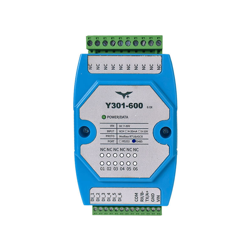 | 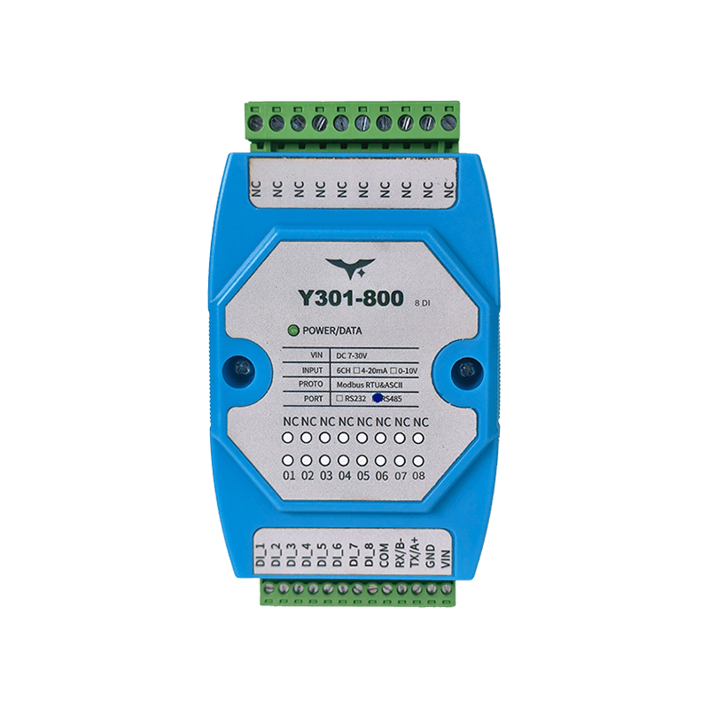 | 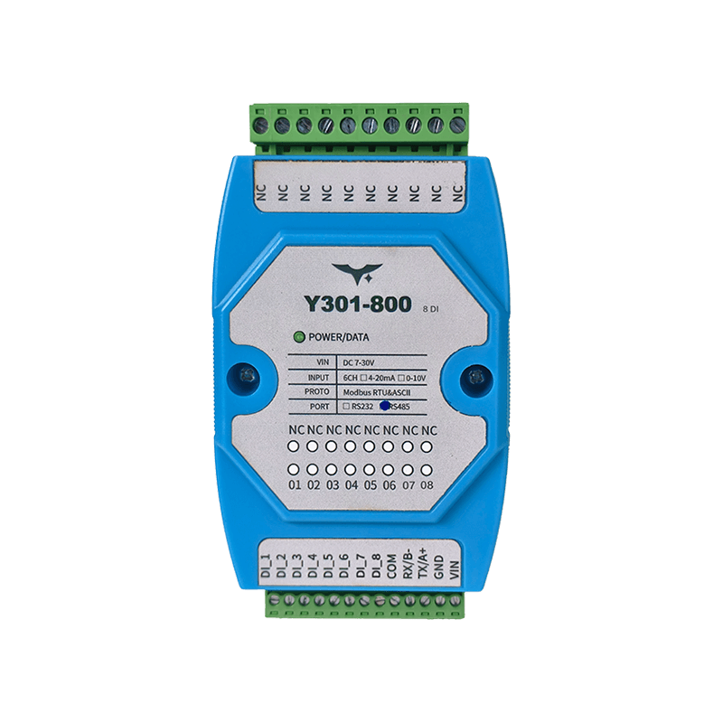 |
Contents
1. Overview
This manual explains the Modbus mapping and typical commissioning commands for the Y301-600, Y301-800, and Y301-G00 digital input modules.
| Model | DI | DO | AI | AO |
|---|---|---|---|---|
| Y301-600 | 6 | 0 | 0 | 0 |
| Y301-800 | 8 | 0 | 0 | 0 |
| Y301-G00 | 16 | 0 | 0 | 0 |
RTU frame format: [slave address][function code][data][CRC low][CRC high]
All commands in this document are shown in hexadecimal.
2. Default Settings
| Parameter | Default |
|---|---|
| Slave address | 1 |
| Broadcast address | 254 |
| Baud rate | 9600 bps |
| Data bits | 8 |
| Parity | None |
| Stop bits | 1 |
| Protocol | Modbus RTU (also compatible with Modbus ASCII) |
3. Modbus Register Map
3.1 Discrete Inputs (DI) - Function Code 0x02
| Channel | PLC Address | PDU Address (0-based) | Supported Models |
|---|---|---|---|
| DI1 | 1x0001 | 0x0000 | Y301-600/800/G00 |
| DI2 | 1x0002 | 0x0001 | Y301-600/800/G00 |
| DI3 | 1x0003 | 0x0002 | Y301-600/800/G00 |
| DI4 | 1x0004 | 0x0003 | Y301-600/800/G00 |
| DI5 | 1x0005 | 0x0004 | Y301-600/800/G00 |
| DI6 | 1x0006 | 0x0005 | Y301-600/800/G00 |
| DI7 | 1x0007 | 0x0006 | Y301-800/G00 |
| DI8 | 1x0008 | 0x0007 | Y301-800/G00 |
| DI9 | 1x0009 | 0x0008 | Y301-G00 |
| DI10 | 1x0010 | 0x0009 | Y301-G00 |
| DI11 | 1x0011 | 0x000A | Y301-G00 |
| DI12 | 1x0012 | 0x000B | Y301-G00 |
| DI13 | 1x0013 | 0x000C | Y301-G00 |
| DI14 | 1x0014 | 0x000D | Y301-G00 |
| DI15 | 1x0015 | 0x000E | Y301-G00 |
| DI16 | 1x0016 | 0x000F | Y301-G00 |
Returned bit definition: 0 = inactive, 1 = active.
3.2 Holding Registers (Configuration Parameters) - Function Code 0x03/0x06
| Parameter | PLC Address | PDU Address (0-based) | Description |
|---|---|---|---|
| Communication baud rate | 4x1001 | 0x03E8 | Baud-rate code (see 3.3) |
| Reserved | 4x1002 | 0x03E9 | Reserved |
| Offset address | 4x1003 | 0x03EA | Device address = offset address + DIP address |
| Operating mode | 4x1004 | 0x03EB | User data register |
| Delay time | 4x1005 | 0x03EC | User data register |
3.3 Baud-Rate Code Table
| Code | Baud Rate (bps) |
|---|---|
| 0 | 9600 |
| 1 | 2400 |
| 2 | 4800 |
| 3 | 9600 |
| 4 | 19200 |
| 5 | 38400 |
4. Command Examples
4.1 Read All DI States by Model
| Model | Request (broadcast address FE) |
|---|---|
| Y301-600 (6DI) | FE 02 00 00 00 06 EC 07 |
| Y301-800 (8DI) | FE 02 00 00 00 08 6D C3 |
| Y301-G00 (16DI) | FE 02 00 00 00 10 6D C9 |
Typical Y301-800 response:
text
Request:  FE 02 00 00 00 08 6D C3
Response: FE 02 01 01 50 5C
The third byte 01 is the byte count. The fourth byte 01 contains DI states; bit 0 is 1, so DI1 is active.
4.2 Read a Single DI Channel (DI1 Example)
text
Request:  01 02 00 00 00 01 B9 CA
Response: 01 02 01 [status byte] [CRC]
4.3 Read All DI States by Slave Address (0x01)
| Model | Request |
|---|---|
| Y301-600 | 01 02 00 00 00 06 F8 08 |
| Y301-800 | 01 02 00 00 00 08 79 CC |
| Y301-G00 | 01 02 00 00 00 10 79 C6 |
4.4 DI Status Byte Mapping
- First status byte:
bit0-bit7map toDI1-DI8 - Second status byte (
16DIonly):bit0-bit7map toDI9-DI16
5. Parameter Configuration
5.1 Read and Write the Offset Address (4x1003)
Read the offset address:
text
Request:  01 03 03 EA 00 01 A5 BA
Response: 01 03 02 00 01 [CRC]    // example: current offset address = 1
Set the offset address to 5:
text
Request:  01 06 03 EA 00 05 68 79
Response: 01 06 03 EA 00 05 68 79
5.2 Read and Write the Baud Rate (4x1001)
Read the baud-rate code:
text
Request:  01 03 03 E8 00 01 04 7A
Response: 01 03 02 00 03 [CRC]    // example: code = 3
Set the baud-rate code to 4 (19200 bps):
text
Request:  01 06 03 E8 00 04 08 79
Response: 01 06 03 E8 00 04 08 79
After changing the baud rate, restart the device and update the host serial settings accordingly.
5.3 Addressing and Bus Recommendations
- Address
254is the manufacturer's setup address, which receives responses. Use it with one device on the bus; it differs from standard Modbus broadcast address0. - In multi-drop networks, every device must use a unique slave address. Do not use the broadcast address for normal polling.
- Address
0is not used for normal communication.
6. Troubleshooting
| Symptom | Possible Cause | Recommendation |
|---|---|---|
| Cannot read DI status | Address or baud rate mismatch | Verify address, baud rate, and parity settings |
| No RS485 response | Reversed A/B wiring or missing ground reference | Check A/B polarity and common ground; add termination if needed |
| No RS232 response | Serial pinout mismatch | Verify the TX/RX/GND connection against the host definition |
| Abnormal response on multi-drop bus | Address conflict or use of broadcast polling | Assign a unique address to each device and disable broadcast polling |
LED Indicator
| LED | Status | Meaning |
|---|---|---|
| POWER | Solid on | Power is normal |
- Manufacturer: Hunan YenGear Tech Co., Ltd.
- Address: Room 21014, Building 1, Fudi Xingguang Tiandi, Yingxin Road, Yuhua District, Changsha, Hunan, China
- Email: [email protected]
- Website: www.yengear.com