
Appearance
Dual-Output Temperature Switch Specification
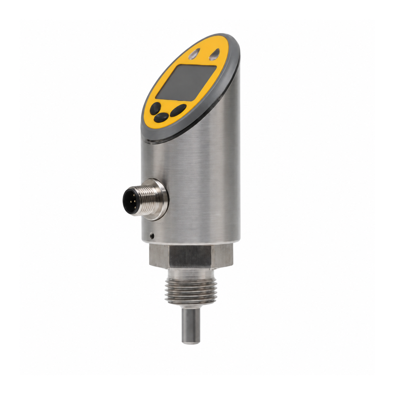
Overview
This temperature switch has a Pt1000 measuring element, a local display, and two configurable outputs. Set one temperature alarm, two independent alarms, or a window alarm with upper and lower limits.
The threaded probe configuration has a four-pin connector. For liquid temperatures above 100 °C, use a separate electronic head with a suitable external probe and keep the head at normal ambient temperature.
Technical Specifications
| Parameter | Specification |
|---|---|
| Measurement range | -50 to 150 °C; select the probe and structure for the process temperature |
| Measuring element | Pt1000 |
| Specified measurement accuracy | 0.5 °C |
| Supply voltage | 24 V DC ±10% |
| Device operating current | <100 mA; budget connected loads separately |
| Switching outputs | 2 when both ports are configured for switching |
| Output type | NPN, PNP, or push-pull, configurable |
| Switching current | 250 mA specified rating; per-channel, combined-load, and inductive-load limits require confirmation |
| Switch-point range | -49.8 to 150 °C |
| Reset-point range | -50 to 149.8 °C |
| Minimum SP/rP separation | 0.2 °C |
| Switching setting resolution | 0.1 °C |
| Output behavior | NO/NC; hysteresis or window; configurable fault output |
| OUT1 | Switching or configuration interface |
| OUT2 | Switching or 4–20 mA / 20–4 mA |
| Electrical connector | M12 A-coded, 4 pins |
| Process connection | G1/2 male |
| Housing / probe material | 304 stainless steel / 316L stainless steel |
| Ambient operating temperature | -40 to 80 °C |
| Protection rating | IP65 |
OUT2 supplies either an analog signal or a switching signal. Set it to switching mode for two independent alarms.
Setting the Thresholds
- Enter the local setting menu with the mode button.
- Set SP1 and rP1 for output 1. Set SP2 and rP2 if output 2 is used for switching.
- Select the output type, NO/NC behavior, and hysteresis or window mode.
- Select the required fault-output state.
- Save and return from the menu. Accepting an individual value does not save the complete configuration.
SP must be higher than rP. Observe the minimum separation and the range limits when changing settings.
| Alarm example | Settings | Output behavior to test |
|---|---|---|
| One high-temperature alarm | Output 1: PNP, NO, hysteresis; SP1 = 60 °C, rP1 = 55 °C | High-temperature state near 60 °C; reset near 55 °C |
| Separate low/high alarms | Output 1: NC hysteresis, SP1 = 22 °C, rP1 = 20 °C; output 2: NO hysteresis, SP2 = 60 °C, rP2 = 55 °C | Two independent temperature conditions |
| Combined window alarm | Window mode; lower boundary 20 °C, upper boundary 60 °C; choose output polarity | One state for values outside or inside the window |
Choose alarm values for the process. Test output behavior at the boundaries, after power-up, and after a sensor fault.
Connector Functions
| Pin | Function |
|---|---|
| 1 | Supply positive |
| 2 | OUT2 |
| 3 | 0 V |
| 4 | OUT1 / configuration interface |
Set each PNP output to switching mode and use a signal relay between it and the wireless digital input. See Wireless I/O Integration.
Installation and Ordering
Specify the measured medium, temperature range, connection, insertion length, material, and output use. The probe needs suitable immersion or thermal contact. Allow for thermal response and process temperature gradients when setting alarm margins.
Related document: Sensors.