
Appearance
Submersible Level Controller Specification
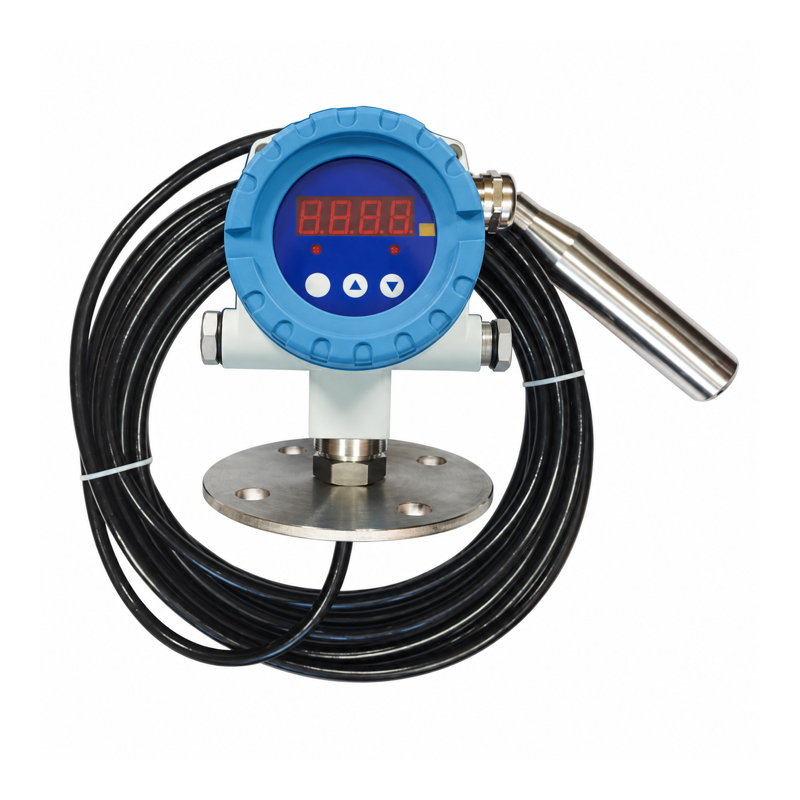
Overview
This controller measures liquid level with a submerged hydrostatic probe and shows the reading on a separate electronic head. The two-alarm configuration has independently adjustable relay outputs for high and low level alarms.
Use both relays for separate alarms or one relay for a single alarm.
Technical Specifications
| Parameter | Specification |
|---|---|
| Measurement principle | Hydrostatic pressure |
| Measuring-range selection | 0.3–100 m range options; select the full-scale depth for the installation |
| Supply voltage | 24 V DC |
| Device power | ❤️ W; check the rating for the selected configuration |
| Switching outputs | 2 relay alarms |
| Settings | Numeric pickup and release values for each relay |
| Alarm direction | High or low level, defined by pickup/release settings |
| Display | LED numeric display |
| Electrical connection | Terminals at the controller head |
| Additional signal | 4–20 mA; communication available in selected configurations |
Liquid density affects the conversion from probe pressure to level. For liquids other than water, specify the medium and density when ordering. Choose compatible probe and cable materials.
Level Thresholds
Set each relay's pickup and release values in the configured level units. Their difference provides hysteresis to reduce contact chatter.
- For a high-level alarm, pickup is above release.
- For a low-level alarm, pickup is below release.
- Set both channels independently when high and low states must remain distinguishable.
For example, set one alarm to pick up at 400 mm and release below 395 mm. Set the other to pick up below 100 mm and release above a higher reset value. Test the trigger and reset directions in the selected units, then save the settings.
For pump start/stop control, define how the output holds its state between the level limits and after power-up. Two independent alarm outputs alone do not provide this sequence.
Installation and Connection
Install the probe at the intended depth, keep it clear of sediment and strong inlet flow, and preserve the pressure-reference vent where the probe cable uses one. Protect the electronic head and cable termination from moisture.
Wire each isolated alarm contact to one wireless DI and COM. The contact rating, including the minimum switching load, must suit the DI. Follow the terminal drawing for the selected supply and output configuration.
See Wireless I/O Integration for channel allocation and commissioning.
Ordering Information
Specify full-scale depth, medium, density, probe material, cable material and length, controller supply, two-relay output configuration, and alarm/reset values. Obtain the measurement accuracy, probe and head environmental ratings, terminal allocation, and relay contact load limits for that configuration.