
Appearance
Flow and Temperature Switch Specification
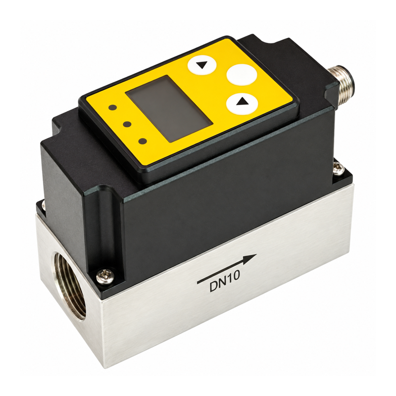
Overview
This inline turbine sensor measures liquid flow and temperature. Select a configuration with one or two alarm outputs. Assign flow or temperature to each alarm.
Use two flow alarms for separate limits, one flow alarm plus one temperature alarm, or a single output in window mode. The selected pipe size and measuring range must cover the required flow limits.
Technical Specifications
| Parameter | Specification |
|---|---|
| Flow measurement principle | Turbine |
| Flow range | Selected with pipe diameter and ordered measuring range |
| Standard temperature measurement range | 0–100 °C |
| Specified temperature accuracy | ≤1 °C |
| Supply voltage | 24 V DC |
| Device power | 3 W; budget connected loads separately |
| Alarm output count | Up to 2, according to output configuration |
| Alarm output type | NPN or PNP |
| Switching capacity | 24 V / 50 mA |
| Alarm assignment | Flow or temperature, separately selectable for each alarm |
| Alarm modes | Disabled, hysteresis NO/NC, or window NO/NC |
| Additional output options | Current outputs or communication; port allocation depends on configuration |
| Display | 128 × 64 OLED |
| Body / wetted base | Aluminum-alloy body / 304 stainless-steel base |
| Protection rating | IP67 |
| Process connections | G1/4, G3/8, G1/2, G3/4, or G1, according to size |
Communication and analog outputs may share ports with the alarm outputs. Specify the required output allocation when ordering. Obtain the alarm response time for that configuration; the display update rate does not specify switching response.
Adjustable Alarms
Each enabled alarm has a switch value and a reset value. In window mode, these define the upper and lower limits. Select the output type and polarity for each alarm.
For example, set one output to operate above 13 L/min and reset below 12 L/min, and the other to operate above 70 °C and reset below 69 °C. For separate flow limits, assign both outputs to flow. Choose values within the selected measurement range.
Installation
- Keep the measuring pipe completely full and avoid trapped air.
- Follow the marked flow direction.
- Provide at least 10 pipe diameters of straight pipe upstream and 5 downstream for the basic arrangement. Bends, valves, and other disturbances can require longer lengths.
- Filter particles that could obstruct or damage the turbine.
- Flush new piping before installing the sensor.
- Install the unit where it can be inspected and cleaned.
Wireless I/O Connection
Select a signal relay whose input current, including startup, stays within the 50 mA output limit. Also check leakage, voltage drop, and transient suppression; matching the 24 V rating alone is insufficient.
Use one relay and one DI for each independent PNP alarm. Wire only the relay's dry contact to Y401/Y402/Y403 DI and COM. Follow the pin allocation for the selected output configuration.
Ordering Information
Specify the liquid, pipe diameter, flow range and units, temperature range, connections, pressure conditions, output count, alarm assignments, and any additional analog or communication output.