
Appearance
Dual-Output Pressure Switch Specification
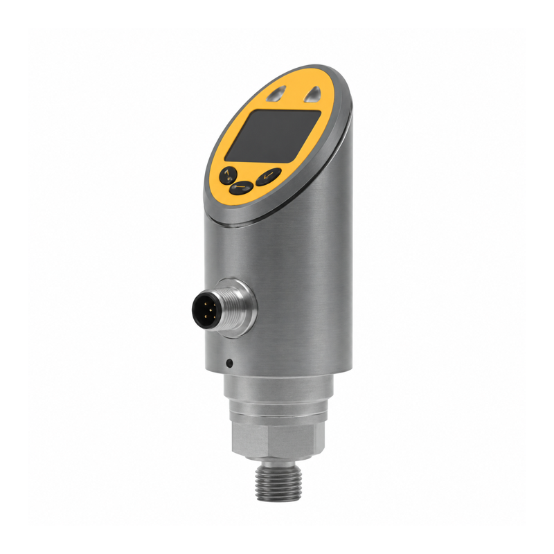
Overview
This pressure switch has a local display and two configurable switching outputs. Set separate pressure alarms or a window alarm. Use one output for a single state or both for two independent states.
The 0–10 bar configuration has a five-pin connector, two switching outputs, and a separate current output.
Technical Specifications
| Parameter | Specification |
|---|---|
| Measuring range | 0–10 bar, equivalent to 0–1 MPa |
| Maximum overpressure for this range | 20 bar |
| Specified accuracy | 0.5% |
| Supply voltage | 24 V DC ±10% |
| Device operating current | <100 mA; budget connected loads separately |
| Switching outputs | 2; configurable NPN, PNP, or push-pull |
| Switching output current | 250 mA specified rating; per-channel, combined-load, and inductive-load limits require confirmation |
| Output behavior | NO/NC; hysteresis or window mode |
| Switch-point range | 0.05–10 bar |
| Reset-point range | 0–9.95 bar |
| Minimum SP/rP separation | 0.05 bar for the specified range |
| Switching setting resolution | 0.01 bar |
| Additional analog output | 4–20 mA |
| Configuration | Local buttons; configuration interface available |
| Electrical connector | M12 A-coded, 5 pins |
| Process connection | G1/4 male |
| Housing | Stainless steel |
| Ambient operating temperature | -40 to 80 °C |
| Protection rating | IP65 |
Setting resolution describes the adjustment step; accuracy describes the measurement. Keep normal process pressure within the measuring range. The overpressure rating is a limit, not an operating target.
Adjustable Alarm Behavior
Each output has an independent switch point and reset point. Select hysteresis mode for a stable high- or low-limit state, or window mode for an interval alarm. Choose NO/NC behavior and the output state required during a detected sensor fault.
For example, set a high-pressure alarm to switch near 6 bar and reset near 5.5 bar. The second output can report low pressure with separate settings. Choose alarm values for the equipment and pressure range.
Electrical Connections
| Connector pin | Function |
|---|---|
| 1 | Supply positive |
| 2 | OUT2 switching output |
| 3 | 0 V |
| 4 | OUT1 switching output / configuration interface |
| 5 | 4–20 mA output |
Set OUT1 to switching mode when it drives a signal relay. Match the cable to the connector pin numbers; wire colors alone do not identify the functions.
For PNP operation with Y401/Y402/Y403, use one signal relay per independent alarm. Wire each relay's dry contact to DI and COM. See Wireless I/O Integration.
Installation and Ordering
Specify pressure range and reference type, process connection, medium, seal compatibility, output configuration, and cable. Select the range so both alarm values and the expected process peaks fit the pressure limits.
Check the local display, both outputs, fault response, and parameter retention before placing the equipment in service.