
Appearance
Float Level Controller Specification
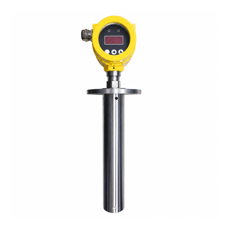
Shown with a protective tube. Probe and mounting assemblies depend on the ordered configuration.
Overview
This controller measures liquid level with a float that moves along a stem. It has a local display and two adjustable relay alarms for separate high and low level states. Use one relay for a single alarm.
The two-alarm configuration uses a 24 V DC supply. Choose the stem length, float, and wetted materials for the tank and medium.
Technical Specifications
| Parameter | Specification |
|---|---|
| Measurement principle | Float-based level detection |
| Measuring-length options | 150–2000 mm; active measuring interval depends on the probe configuration |
| Supply voltage | 24 V DC |
| Device power | ❤️ W; check the rating for the selected configuration |
| Switching outputs | 2 relay alarms |
| Alarm settings | Independent numeric pickup and release values |
| Alarm direction | High or low level, determined by the two values for each relay |
| Local indication | LED numeric display |
| Connection | Terminals at the electronic head |
| Additional signal | 4–20 mA; communication available in selected configurations |
Obtain the measurement resolution and accuracy for the selected probe. Display resolution alone does not indicate measurement accuracy.
Alarm Settings
For each channel, enter the required pickup and release values. A pickup value above release produces a high-level alarm; a pickup value below release produces a low-level alarm. The separation provides hysteresis.
Use the configured level units, save and exit the menu, and test each output through its pickup/reset cycle. The two relays provide independent alarms; this configuration has no specified single-output window mode.
Tank Installation
The float must move freely throughout the active measuring interval. Check available headroom, stem mounting, tank geometry, turbulence, deposits, and the medium's density and viscosity. Select float and wetted materials compatible with the liquid and its temperature.
Keep the electronic head within its environmental limits and protect terminal connections from moisture.
Wireless I/O Connection
Wire each electrically isolated alarm contact to DI and COM on the wireless module. Two independent alarm states need two DIs. Check the relay contact load limits, including the minimum switching load.
Ordering Information
Specify measuring length and active interval, medium, density, float and stem materials, mounting connection, supply, two-relay configuration, cable entry, and alarm/reset values. Check the assembly dimensions against the tank and obtain the measuring performance for the selected probe.