
Appearance
Y331-0020/0040/0060/0080 Fully Isolated Multi-Range Analog Input Modules Specification
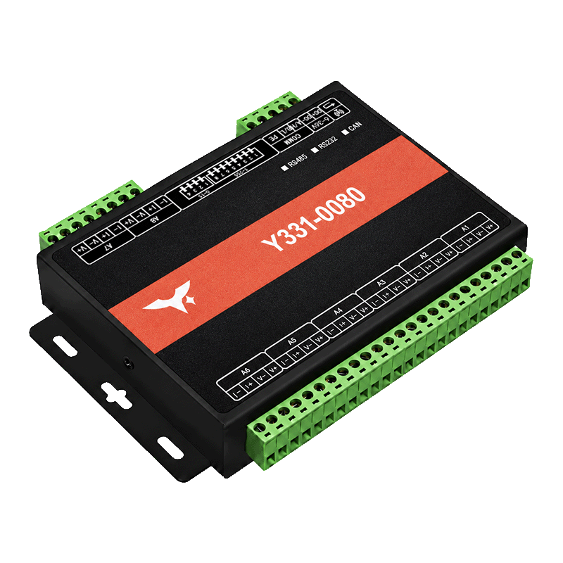
Contents
- Overview
- Ordering Information
- Key Features
- Technical Specifications
- Interfaces and Pinout
- Mechanical and Environmental
1. Overview
The Y331 fully isolated multi-range analog input modules belong to the YenGear Serial I/O Modules family. They provide 2, 4, 6, or 8 analog inputs for DC voltage and current acquisition.
Each input channel is isolated from the other input channels. Signal options cover millivolt, voltage, milliamp, and ampere ranges.
2. Ordering Information
2.1 Model Configuration
The four positions after Y331- follow DI / DO / AI / AO. Retain all four positions, including the final zero. Y331-0080 means 0 DI, 0 DO, 8 AI, and 0 AO.
| Model | DI | DO | AI | AO |
|---|---|---|---|---|
| Y331-0020 | 0 | 0 | 2 | 0 |
| Y331-0040 | 0 | 0 | 4 | 0 |
| Y331-0060 | 0 | 0 | 6 | 0 |
| Y331-0080 | 0 | 0 | 8 | 0 |
2.2 Interface Options
| Interface | Configuration |
|---|---|
| Isolated RS485 | Default; Modbus RTU |
| RS232 | Optional |
| Isolated CAN | Optional |
Specify the interface with the model when ordering.
2.3 Input Range Options
| Signal type | Available ranges |
|---|---|
| DC voltage | 0-100 mV, 0-500 mV, 0-5 V, 0-10 V, 0-30 V |
| DC current | 0-20 mA, 4-20 mA, 0-2 A, 0-10 A |
Choose an input range when ordering.
3. Key Features
- Separate voltage and current terminals for each channel
- DIP switches for address and baud-rate settings
- Watchdog and electrical protection against reverse polarity, overcurrent, overvoltage, surges, and ESD
4. Technical Specifications
4.1 Power and Protection
| Parameter | Specification |
|---|---|
| Supply voltage | 6-36 VDC |
| Supply current | <1 A |
| Protection | Reverse polarity, overcurrent, overvoltage, surge, and ESD |
4.2 Analog Input
| Parameter | Specification |
|---|---|
| Channel count | 2, 4, 6, or 8 AI |
| ADC resolution | 12 bits |
| Internal ADC sampling rate | 200 kHz per channel |
| Data update rate | 30 Hz per channel |
| Voltage input ranges | 0-100 mV, 0-500 mV, 0-5 V, 0-10 V, 0-30 V |
| Current input ranges | 0-20 mA, 4-20 mA, 0-2 A, 0-10 A |
| Voltage resolution | 0-500 mV: 0.01 mV; 0-5 V / 0-10 V / 0-30 V: 1 mV |
| Current resolution | 0-20 mA / 4-20 mA: 1 µA; 0-2 A / 0-10 A: 1 mA |
| Voltage accuracy | ±0.1% |
| Milliamp input accuracy | ±0.1% |
| Ampere input accuracy | ±1% |
4.3 Isolation
| Item | Specification |
|---|---|
| Input channel isolation | Channel-to-channel |
| Communication isolation | RS485 and CAN interface options |
4.4 Communication
| Parameter | Specification |
|---|---|
| RS485 protocol | Modbus RTU |
See the Technical Manual for RS485 settings, register addresses, and commissioning.
5. Interfaces and Pinout
5.1 Terminal Overview
| Group | Terminals / Function |
|---|---|
| Power | DC+ / DC-: supply positive / negative, 6-36 VDC |
| Voltage input | V+ / V-: positive / negative for each channel |
| Current input | I+ / I-: positive / negative for each channel |
| Communication | A/H / B/L: use the interface-specific terminal drawing for pin assignments |
| Earth | PE: follow the model-specific wiring drawing |
| Hardware settings | DIP switches for address and baud-rate settings |
| Indicators | PWR power indicator; RUN, BAT, ERR, and numbered channel indicators |
5.2 Wiring Guidelines
- Use the voltage or current terminals that match the ordered range.
- Keep each channel's input pair separate to preserve channel isolation.
- Follow the model-specific power, earth, and communication terminal labels.
See the Technical Manual for RS485 commissioning and configuration.
6. Mechanical and Environmental
| Item | Specification |
|---|---|
| Mounting | Screw mounting |
| Operating temperature | -40 to +85 °C |
Enclosure Dimensions
| Model | Dimensions (mm) |
|---|---|
| Y331-0080 | Approx. 162.5 × 100 × 26 |
Use the mechanical drawing for the ordered range and interface when planning mounting clearances.
- Manufacturer: Hunan YenGear Tech Co., Ltd.
- Email: [email protected]
- Website: www.yengear.com