
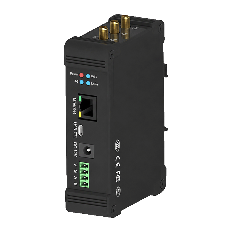
Appearance
Y511-L LoRaWAN Indoor Edge Gateway Specification
User Manual: Y511-L User Manual
Contents
- Overview
- Model Configurations
- Key Features
- Technical Specifications
- Interfaces and Indicators
- Mechanical and Environmental
- Ordering and Deployment Notes
1. Overview
Y511-L is an indoor LoRaWAN gateway with local network-service and edge-integration capabilities. It forwards encrypted LoRaWAN traffic to an external Network Server or processes end-device data locally through an optional built-in NS/AS service.
The gateway supports JavaScript data processing, application integration through MQTT, HTTP, TCP, or WebSocket, and Modbus TCP/RTU integration for industrial systems.
| Item | Description |
|---|---|
| Product type | Indoor LoRaWAN gateway with edge integration |
| Supported end-device LoRaWAN versions | LoRaWAN 1.0.2 / 1.0.3 / 1.0.4 |
| Supported end-device classes | Class A / Class C |
| Default frequency plan | CN470 |
| Supported frequency plans | CN470, EU433, EU868, AU915, IN865, AS923, RU864, US915 |
| Backhaul | 10/100 Ethernet and Wi-Fi; optional 4G |
| Application interfaces | MQTT, HTTP, TCP, WebSocket, Modbus TCP/RTU, according to software configuration |
| Operating environment | Indoor |
2. Model Configurations
| Configuration | Receive channels | Downlink channels | Selection profile |
|---|---|---|---|
| Y511-L, 8-channel | 8 | 1 | Lower concurrent radio traffic |
| Y511-L, 16-channel | 16 | 2 | More receive channels; two transmit paths |
The channel count describes radio paths, not the maximum number of end devices. Capacity depends on airtime, reporting intervals, payload size, interference, and downlink traffic. Two transmit paths do not guarantee twice the downlink capacity; regional limits, duplex mode, and server scheduling still apply.
3. Key Features
- Supports LoRaWAN 1.0.2, 1.0.3, and 1.0.4.
- Supports Class A and Class C end devices.
- Provides 8 or 16 LoRa receive channels and 1 or 2 downlink channels.
- Provides up to
27 dBmtransmit power and receiver sensitivity down to-140 dBm @ SF12, BW125 kHz. - Supports remote Network Server packet forwarding, with local NS/AS available in the ordered software configuration.
- Supports JavaScript scripts for payload decoding, message transformation, downlink adaptation, scheduled acquisition, and local linkage control.
- Supports MQTT, HTTP, TCP, and WebSocket application interfaces in the local-service configuration; supported message directions vary by protocol.
- Supports Modbus TCP register mapping and Modbus RTU integration through the standard RS485 interface on compatible software configurations.
- Supports Ethernet and Wi-Fi as standard backhaul interfaces; 4G is optional, with configurable network priority where enabled.
- Supports local Web configuration, local upgrade, and remote configuration or upgrade where enabled.
The Network Server manages end-device activation and sessions. In forwarding mode, the gateway transports radio packets; local NS/AS functions require the corresponding software configuration. NS means Network Server; AS means Application Server.
4. Technical Specifications
4.1 LoRaWAN Radio
| Parameter | Specification |
|---|---|
| Frequency plans | CN470 (default), EU433, EU868, AU915, IN865, AS923, RU864, US915 |
| Supported end-device LoRaWAN versions | 1.0.2 / 1.0.3 / 1.0.4 |
| Supported end-device classes | Class A / Class C |
| Channel configurations | 8 RX / 1 TX or 16 RX / 2 TX |
| Transmit power | Up to 27 dBm |
| Receiver sensitivity | Down to -140 dBm @ SF12, BW125 kHz |
| Radio hardware bandwidth range | 7.8 to 500 kHz; usable LoRaWAN settings depend on the regional plan |
| Spreading factor | SF7 to SF12 |
| Reference range | Up to 12 km line of sight and up to 5 km in urban environments; actual range varies with antennas, interference, installation, and site conditions |
4.2 Network and Application Interfaces
| Interface or function | Specification |
|---|---|
| Ethernet | 10/100 Mbps RJ45 |
| Wi-Fi | 2.4 GHz, AP+STA mode, IEEE 802.11 b/g/n |
| 4G | Optional; module and operator-band coverage vary by ordered variant |
| RS485 | Standard RS485 A/B interface for Modbus-RTU on compatible software configurations |
| USB | MicroUSB USB-TTL debug and log interface |
| SIM card | Standard SIM card on 4G configurations |
| Application protocols | MQTT, HTTP, TCP, WebSocket in the local-service configuration |
| Industrial integration | Modbus TCP/RTU server exposing mapped end-device registers to a PLC/master, on compatible software |
4.3 Electrical
| Parameter | Specification |
|---|---|
| Supply | DC 9 to 28 V, typical DC 12 V |
| Maximum current | 1.25 A at a DC12V supply |
| Average power | ≤5 W |
| Maximum power | Up to 15 W for the higher-power 16-channel full-duplex configuration |
5. Interfaces and Indicators
5.1 Main Interfaces
The connector arrangement varies by ordered channel, backhaul, and field-interface configuration.
| Interface | Function |
|---|---|
| DC power input | DC 9–28 V; 5.5 × 2.1 mm jack and parallel power terminals |
| Enclosure ground | Protective earth connection |
| Ethernet | Network backhaul, local management, and Modbus TCP integration |
| LoRa antenna connector | LoRaWAN radio antenna |
| Wi-Fi antenna connector | Wi-Fi antenna |
| 4G antenna connector | Optional cellular antenna |
| RS485 A/B | Standard Modbus-RTU and field-integration interface |
| SIM card slot | Optional cellular connection |
| Factory reset | Restores the configured factory settings |
5.2 Indicators
| Indicator | Meaning |
|---|---|
| Power | Power status |
| Wi-Fi | Blinking: starting; steady: started; off: not started or failed |
| 4G | Cellular network search, standby, and data status on 4G variants |
| LoRa | Steady: radio started; off: not started or failed. This does not confirm server connectivity. |
6. Mechanical and Environmental
| Parameter | 8-channel configuration | 16-channel configuration |
|---|---|---|
| Dimensions | 120.4 × 79.7 × 34 mm | 125.5 × 120.4 × 34 mm |
| Weight | Approximately 1 kg | Approximately 1.5 kg |
| Operating temperature | -20 to 70 °C | -20 to 70 °C |
| Storage temperature | -40 to 85 °C | -40 to 85 °C |
| Humidity | 0 to 95% RH, non-condensing | 0 to 95% RH, non-condensing |
| Installation | DIN rail or wall mounting, according to the supplied bracket | DIN rail or wall mounting, according to the supplied bracket |
7. Ordering and Deployment Notes
- Select the RF frequency plan, channel configuration, and half- or full-duplex hardware when ordering. The default plan is
CN470. ForAS923, specify the sub-plan. - Match the gateway frequency plan and channel group with the end devices and the Network Server.
- Confirm the 4G and application-interface options in the order configuration before delivery; RS485 is standard.
- Use a suitable external LoRa antenna and install it before powering the gateway.
- Keep application credentials, device keys, and server certificates out of screenshots, public documents, and support logs.
- Connector set, cellular module, antenna count, and software options vary by ordered configuration.
YenGear
Hunan YenGear Tech Co., Ltd.
Room 21014, Building 1, Fudi Xingguang Tiandi, Yingxin Road, Yuhua District, Changsha, Hunan, China
[email protected] · www.yengear.com