
Appearance
Level and Temperature Switch Specification
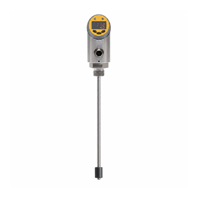
Overview
This sensor measures float position and temperature in a compact tank. Set both ports to switching mode for one temperature output and one level output. Each supports adjustable hysteresis or window limits.
Use the level output for one level alarm or for a combined upper/lower window state. Separate high-level and low-level signals require a controller with two level outputs, such as the Float Level Controller.
Technical Specifications
| Parameter | Specification |
|---|---|
| Standard stem lengths | 250 mm or 500 mm |
| Active level measuring interval | 40 mm to stem length minus 40 mm |
| Active interval for 250 mm stem | 40–210 mm |
| Active interval for 500 mm stem | 40–460 mm |
| Level principle | Magnetic float-position measurement |
| Specified level accuracy | 5 mm |
| Level switch-point range | 45 mm to stem length minus 40 mm |
| Level reset-point range | 40 mm to SP2 minus 5 mm |
| Minimum level setting separation | 5 mm |
| Float material | NBR |
| Temperature element | Pt1000 |
| Temperature measurement range | -50 to 150 °C; check process and float limits for the medium |
| Specified temperature accuracy | 0.5 °C |
| Temperature switch / reset ranges | -49.8 to 150 °C / -50 to 149.8 °C |
| Temperature setting resolution / minimum separation | 0.1 °C / 0.2 °C |
| Supply voltage | 24 V DC ±10% |
| Device operating current | <200 mA; budget connected loads separately |
| Output type | NPN, PNP, or push-pull, configurable |
| Switching current | 250 mA specified rating; per-channel, combined-load, and inductive-load limits require confirmation |
| OUT1 | Temperature switch or configuration interface |
| OUT2 | Level switch or level 4–20 mA / 20–4 mA |
| Output modes | NO/NC; hysteresis or window |
| Connector | M12 A-coded, 4 pins |
| Process connection | G1/2 |
| Protection rating | IP65 |
The active measuring interval excludes the first and last 40 mm of the stem. Keep thresholds within that interval and leave the required separation between limits.
Setting the Outputs
- Set SP1/rP1 for temperature output 1.
- Set SP2/rP2 for level output 2.
- Select hysteresis or window mode separately for each output.
- Choose switching mode for OUT2 when a physical level alarm is required.
- Set output polarity and fault behavior, then save and exit the menu.
For a level window, SP2 sets the upper boundary and rP2 the lower boundary. The receiving module gets one combined state, without identifying which limit the level crossed.
The display offset changes the level reading on screen. Switching thresholds and the analog signal keep their original reference. Establish that reference before setting the alarms.
Connector Functions
| Pin | Function |
|---|---|
| 1 | Supply positive |
| 2 | OUT2, level |
| 3 | 0 V |
| 4 | OUT1, temperature / configuration interface |
Each PNP alarm sent through wireless I/O needs a signal relay. Use two DIs for separate level and temperature states, or one DI for the level window state alone.
Installation and Ordering
Specify stem length, tank dimensions, liquid density, medium compatibility, float material, mounting connection, and operating temperature. Allow the float to move freely and keep the head and connector within their environmental limits.