
Appearance
OLED Pressure Switch Specification
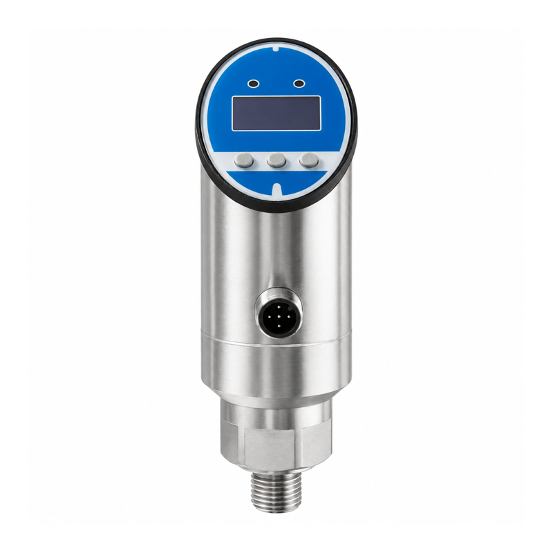
Overview
This pressure switch has an OLED display, two PNP switching outputs, and a current output. Set a single alarm, two separate alarms, or window limits at the device.
Gauge-pressure options have full-scale values from 100 kPa to 60 MPa. Absolute-pressure options use separate ranges. Specify the pressure reference and full-scale range when ordering.
Technical Specifications
| Parameter | Specification |
|---|---|
| Pressure reference | Gauge or absolute, selected with the range |
| Accuracy for standard ranges | ±0.5% of full scale |
| Overload pressure | Depends on the selected range |
| Supply voltage | 12–30 V DC |
| Switching outputs | 2 PNP |
| Additional analog output | 0/4–20 mA |
| Switching response | <10 ms; sensor response does not specify wireless-system delay |
| Adjustable switching delay | 0.0–99.9 s |
| Switching modes | Hysteresis or window, NO/NC selectable |
| Switch-on or upper-limit setting | 1.5–100% of full scale |
| Reset or lower-limit setting | 1–99.5% of full scale |
| Minimum setting separation | 0.5% of full scale |
| Display / controls | 128 × 64 OLED; 3 buttons |
| Pressure display units | MPa, kPa, bar, psi, kgf/cm² |
| Operating temperature | -20 to 80 °C |
| Protection rating | IP65 |
| Electrical connector | M12, 5 pins; switching and current outputs |
Relay selection requires the per-channel and combined output-current limits, including inductive-load requirements. Obtain these limits for the selected configuration before choosing the relays.
Alarm Configuration
Set the switch and reset values for each output. Their difference sets the hysteresis band; in window mode, they define the upper and lower limits. Adjust the switching delay as required.
Full-scale range affects the minimum separation. For example, 0.5% of a 10 bar full-scale range is 0.05 bar. Choose a range that gives useful alarm spacing for the application.
Connector Functions
| Pin | Function |
|---|---|
| 1 | Supply positive |
| 2 | Switching output 1 |
| 3 | 0 V |
| 4 | Switching output 2 |
| 5 | Current output |
The five-pin connector carries two switching outputs and one current output. Communication variants use a different interface and wiring diagram.
Wireless I/O Connection
Use a compatible signal relay for each PNP output. Wire its isolated dry contact to Y401/Y402/Y403 DI and COM. One alarm needs one DI; two independent alarms need two DIs.
See Wireless I/O Integration for electrical checks and channel selection.
Ordering Information
Specify range, gauge or absolute pressure, connection thread, seal material, compatible medium, electrical configuration, and cable. Confirm overload pressure and the required alarm values for the selected range.