
Appearance
Y201C CAN-to-Serial Gateway Specification
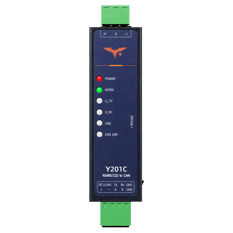
Reference: Y201C Technical Manual
Y201C is a single-CAN industrial gateway for bidirectional data transfer between one CAN 2.0 A/B bus and one serial port. The model does not include Ethernet or additional CAN channels.
Contents
- Overview
- Ordering Information
- Key Features
- Technical Specifications
- Interfaces and Indicators
- Mechanical
- Application Notes
1. Overview
Y201C transfers data bidirectionally between one CAN 2.0 A/B bus and one serial port. The ordered serial variant uses RS232, RS485, or TTL. The TTL voltage level is not specified; verify it for the ordered variant before wiring. The gateway supports data-only, ID-plus-data, complete-frame, and Modbus RTU conversion modes.
Application areas include charging equipment, automotive electronics, industrial automation, fire protection, and industrial production.
| Item | Description |
|---|---|
| Product Type | Industrial CAN-to-serial gateway |
| CAN Interface | One CAN 2.0A / CAN 2.0B channel |
| Serial Interface | One RS232, RS485, or TTL port, depending on the ordered variant |
| Supply Voltage | 5 to 36 VDC |
| CAN Baud Rate | 10 to 1000 kbps, default 100 kbps |
| Configuration | Configuration tool or serial AT commands |
Highlights
- Bidirectional CAN-to-serial transparent transmission
- Supports CAN standard and extended frames, data frames, and remote frames
- Supports serial-to-CAN data, ID-plus-data, and complete-frame formats
- Converts validated Modbus RTU frames to segmented CAN data and reconstructs CAN data for serial output
- Built-in
120 ΩCAN termination with switch configuration - Eight configurable CAN filters for the single CAN channel
- Serial and CAN heartbeat packets for link and device monitoring
5 to 36 VDCindustrial power input with reverse-polarity protection- Hardware watchdog, serial firmware upgrade, and backup-parameter recovery
2. Ordering Information
2.1 Model Configuration
Y201C is a single-CAN gateway. Select the serial electrical interface when ordering:
RS232for point-to-point serial devicesRS485for differential multi-drop busesTTLfor embedded controller connections; check the voltage level for the ordered variant
Each unit has one serial electrical interface. It does not expose all three interfaces at the same time.
2.2 Configuration
| Model | Serial Interface | Description |
|---|---|---|
| Y201C | RS232 / RS485 / TTL | Single-CAN gateway with serial AT configuration and bidirectional CAN-to-serial transfer |
3. Key Features
- CAN 2.0 A/B Frames: Standard and extended frames, data frames, and remote frames.
- Bidirectional Transfer: Moves data between the CAN bus and the ordered serial interface.
- Frame Formats: Data-only, ID-plus-data, and complete-frame serial formats.
- Modbus Conversion: Converts valid Modbus RTU traffic to segmented CAN data without acting as a Modbus master or slave.
- CAN Filtering: Eight independent filters for the single CAN channel, with frame-format, ID, and mask conditions.
- CAN Tools: Configurable CAN heartbeat frames, loopback testing, and packet splitting.
- Serial Configuration: Configurable baud rate, parity, data bits, stop bits, packetization, and serial heartbeat.
- Maintenance: Configuration tool, serial AT commands, firmware upgrade, backup parameters, and factory reset.
4. Technical Specifications
4.1 Electrical and Environmental
| Parameter | Specification |
|---|---|
| Supply Voltage | 5 to 36 VDC |
| Power Connector | Pluggable terminal block |
| Operating Current | 60 mA average at 12 V |
| Operating Temperature | -40 to 85 °C |
| Operating Humidity | 5 to 95% RH |
| Reverse-Polarity Protection | Supported |
4.2 CAN Specifications
| Parameter | Specification |
|---|---|
| CAN Channels | One |
| Protocol | CAN 2.0A / CAN 2.0B |
| Frame Types | Standard / extended; data / remote |
| Baud Rate | 10 to 1000 kbps, default 100 kbps |
| Common Baud Rates | 10, 20, 50, 100, 125, 250, 500, 800, and 1000 kbps |
| Transmit Capacity | Up to 8000 frames/s per channel |
| Receive Capacity | Up to 8000 frames/s per channel |
| CAN Buffer | 1000 packets per channel |
| Termination | Built-in 120 Ω, switch configurable |
| CAN Working Modes | Normal / loopback |
| CAN Filters | Eight per channel |
The supported rate list may differ by firmware. Query the target firmware before using 800 kbps.
4.3 Serial Specifications
| Parameter | Specification |
|---|---|
| Interface Type | RS232, RS485, or TTL, depending on the ordered variant; verify the TTL voltage before wiring |
| Working Modes | AT command mode / transparent mode, transparent mode by default |
| Baud Rate | 1200 to 460800 bps, default 115200; some firmware reports a lower limit of 2400 bps |
| Parity | NONE / ODD / EVEN, default NONE |
| Data Bits | 7 / 8, default 8 |
| Stop Bits | 1 / 2, default 1 |
| Hardware Flow Control | NFC or 485; NFC is the AT-command default |
Query the target firmware before using 1200 bps.
4.4 Data and Maintenance Functions
| Item | Specification |
|---|---|
| Serial Packet Interval | 1 to 300 ms, default 5 ms |
| Serial Packet Length | 1 to 1024 bytes, default 1024; some firmware reports 64 to 1460 bytes, default 1460 |
| Modbus RTU Frame Length | Up to 219 bytes |
| Serial Heartbeat Interval | 1 to 86400 s, default 60 s |
| Serial Heartbeat Data | User-defined hexadecimal string, 2 to 64 bytes |
| CAN Heartbeat Interval | 10 to 86400000 ms, default 60000 ms |
| CAN Heartbeat Data | User-defined hexadecimal string, 2 to 16 bytes |
| Firmware Upgrade | Serial upgrade through the Reload button and configuration tool |
Use the range reported by the configuration tool or the target firmware's AT+UARTTL1=? response during commissioning.
5. Interfaces and Indicators
5.1 Hardware Interfaces
| Interface | Port / Label | Description |
|---|---|---|
| Power Input | + / - | 5 to 36 VDC input |
| Serial Port | TX / A | RS232/TTL transmit or RS485 A |
| Serial Port | RX / B | RS232/TTL receive or RS485 B |
| Serial Ground | GND | Serial signal ground |
| CAN Port | L | CAN differential negative |
| CAN Port | G | CAN signal ground |
| CAN Port | H | CAN differential positive |
| Reload Button | Reload | Hold for 3 to 15 s; behavior is firmware-dependent. AT+RSTCFG restores backup parameters and AT+CLRCFG performs a full factory reset |
| Termination Switch | 1 / 2 | Switches the built-in 120 Ω termination; use the switch assigned to the populated CAN channel |
| Chassis Ground | Grounding screw | Chassis and installation grounding |
For RS485, connect A to A and B to B. For RS232 or TTL, connect TX to the peer RX, RX to the peer TX, and GND to GND.
5.2 LEDs and Status
| Indicator | Meaning |
|---|---|
POWER | Steady on when the device is powered normally |
WORK | Blinks once per second during normal operation; fast blinking indicates serial upgrade mode |
UART TX | Serial data transmission indicator |
UART RX | Serial data reception indicator |
CAN1 | CAN data activity indicator |
CAN1 ERR | CAN error indicator |
5.3 CAN Termination
The gateway provides built-in 120 Ω termination. Enable termination only when the device is installed at a CAN-bus termination point. Keep it disabled when another termination resistor already serves that position.
6. Mechanical
| Parameter | Specification |
|---|---|
| Overall Dimensions | 74 x 30 x 23 mm, excluding mounting tabs |
| Dimension Drawing Reference | Body height 74.25 mm, body width 22.60 mm, mounting-tab width 30 mm; the drawing also labels a 15.60 mm depth |
Check the complete terminal and mounting envelope against the mechanical drawing and the final unit before preparing a panel cutout.
7. Application Notes
- CAN-to-serial transparent transfer: Set the CAN channel target to
UART, selectDATA,ID_DATA, orFRAME, and configure the output frame parameters. - Modbus RTU over CAN: Select
MODBUSmode when the serial side carries validated Modbus RTU frames. The gateway performs protocol validation and forwarding; it does not poll as a Modbus master or respond as a Modbus slave. - Selective CAN reception: Enable one or more of the eight filters when the bus carries unrelated node traffic.
- CAN link testing: Enable loopback for bench testing, then disable it before connecting the gateway to a live bus.
- Heartbeat monitoring: Use serial or CAN heartbeat packets when the host needs periodic link-status or query traffic.
For wiring, AT commands, data formats, and commissioning examples, see the Y201C Technical Manual.
- Manufacturer: Hunan YenGear Tech Co., Ltd.
- Address: Room 21014, Building 1, Fudi Xingguang Tiandi, Yingxin Road, Yuhua District, Changsha, Hunan, China
- Email: [email protected]
- Website: www.yengear.com