
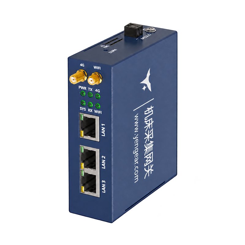
Appearance
FANUC CNC Data Acquisition Gateway Datasheet
Contents
- Overview
- Ordering Information
- Key Features
- Technical Specifications
- Interfaces and Indicators
- Mechanical and Environmental
- Installation and Wiring
1. Overview
The FANUC CNC Data Acquisition Gateway reads machine status, production counts, programs, alarms, and spindle and axis data through the CNC Ethernet interface. It sends data to monitoring and production systems through MQTT or OPC UA.
Typical Applications
CNC status monitoring, production counting, alarm collection, and factory data integration.
2. Ordering Information
Version Selection
| Version | Upstream connectivity | Typical application |
|---|---|---|
| Wi-Fi | Ethernet + Wi-Fi | Factory sites with Wi-Fi coverage |
| 4G | Ethernet + 4G | Sites with cellular coverage and limited factory-network access |
| Wi-Fi + 4G | Ethernet + Wi-Fi + 4G | Sites requiring both wireless connection options |
Selection Details
For selection and quotation, send:
- Required version: Wi-Fi, 4G, or Wi-Fi + 4G.
- FANUC controller series, version, and Ethernet-interface details.
- Required data points and acquisition interval.
- Site network and target MQTT or OPC UA platform.
- Destination country and carrier for a 4G-equipped version.
- Storage expansion, accessories, and program or tool-offset requirements.
The quotation specifies accessories and package contents.
3. Key Features
- Data-point configuration — Individual entry, batch creation, and Excel import.
- Acquisition interval — Configurable polling interval.
- MQTT payloads — Custom topics and script-defined formats.
- Offline storage — Local data storage during network interruptions and automatic forwarding after communication resumes.
- Diagnostics — Browser-based log viewing and network diagnostics.
4. Technical Specifications
Electrical
| Parameter | Specification |
|---|---|
| Supply voltage | 12–24 V DC |
| Supply current | 300 mA; reference voltage and operating condition unspecified |
Communication and Storage
| Parameter | Specification |
|---|---|
| LAN1 protocols | MQTT / OPC UA |
| LAN2 / LAN3 protocols | TCP / UDP / FOCAS |
| CNC interface | FANUC CNC Ethernet interface |
| Configuration | Web browser; LAN1 default address: 192.168.1.230 |
| Storage | Local offline storage; TF card expansion supported |
Supported CNC Controllers
| FANUC controller family | Supported series |
|---|---|
| 0i | C / D / F / M / P / PF series |
| i series | 15i / 16i / 18i / 21i |
| 30 series | 30i / 31i / 32i, Model A / B / C |
| Windows-based systems | 150i / 160i / 180i / 210i / 300i / 310i / Mate320i |
Compatibility requires a FANUC Ethernet interface with the required communication functions enabled. Controller version and CNC configuration determine which data points are available.
Data Acquisition
| Data category | Available data points |
|---|---|
| Machine status | Operating mode, program status, logical equipment state |
| Production | Current quantity, total quantity, target quantity |
| Time counters | Power-on time, running time, cutting time |
| Programs | Main program name and comment; current program name and comment; executing program block; current line number |
| Spindle | Actual and set speed, speed override, temperature, load |
| Feed | Actual and set feed rate, feed override |
| Tools | Tool number |
| Axis position | X / Y / Z machine, absolute, and relative coordinates; remaining travel distance |
| Axis condition | X / Y / Z axis temperature and load |
| Alarms | Alarm message, number, and type |
| Controller information | Controller model and type, axis count, version, serial number, spindle count, and axis names |
During commissioning, check data-point values, units, scaling, and update intervals against the CNC display.
Logical Equipment States
| Value | State |
|---|---|
| 1 | Running |
| 2 | Standby |
| 3 | Alarm |
| 4 | Offline |
5. Interfaces and Indicators
Interface Summary
| Interface | Description |
|---|---|
| Power | 12–24 V DC input |
| LAN1 | Factory-network Ethernet; RJ45, 10/100 Mbps auto-negotiation; default IP 192.168.1.230 |
| LAN2 / LAN3 | CNC-side two-port Ethernet switch; RJ45, 10/100 Mbps auto-negotiation; shared default IP 192.168.0.230 |
| Wi-Fi antenna | Wi-Fi and Wi-Fi + 4G versions |
| 4G antenna / SIM | 4G and Wi-Fi + 4G versions |
| TF card | Storage expansion |
| RESET | Restore factory settings |
LAN2 and LAN3 share the CNC-side network settings.
LED Labels
The product shown has indicators labeled PWR, SYS, TX, RX, 4G, and WIFI.
6. Mechanical and Environmental
| Parameter | Specification |
|---|---|
| Dimensions | 100 × 82 × 30 mm (L × W × H) |
| Weight | 100 g |
| Mounting | DIN rail |
| Operating temperature | −20 to +85 °C |
| Operating humidity | 95% RH, non-condensing |
Compliance — Wi-Fi Version
| Item | Specification |
|---|---|
| CE | Yes |
| Electromagnetic compatibility | EMC Directive 2014/30/EU |
Certification scope for the 4G and Wi-Fi + 4G versions requires confirmation for the supplied configuration.
7. Installation and Wiring
Network Connections
Use LAN1, Wi-Fi, or 4G for the upstream connection, according to version. Connect LAN2 or LAN3 to the CNC. Configure the gateway through its LAN1 IP address or, on Wi-Fi-equipped versions, its Wi-Fi IP address. Set MQTT or OPC UA parameters for the receiving system.
Commissioning
- Mount the gateway on a DIN rail and connect a suitable 12–24 V DC supply.
- Connect a commissioning computer to LAN1 and configure it for the 192.168.1.x subnet with a unique IP address.
- Open
192.168.1.230in a browser to access the configuration interface. - Configure the Ethernet, Wi-Fi, or 4G upstream connection for the selected version and the CNC-side network settings. Restart after changing network-interface IP addresses.
- Add or import the required data points and set the acquisition interval.
- Configure the MQTT or OPC UA connection and verify the received data.
- Check logs, communication diagnostics, and offline storage and forwarding behavior.
YenGear · www.yengear.com · [email protected]