
Appearance
Y301 FlexPoint AI Modules User Manual
Applicable models: Y301-006, Y301-008, Y301-00G.
These modules acquire 6, 8, or 16 analog signals. Each supplied input version has a specified voltage or current range.
Before Wiring
Power off the module and field circuit. The diagrams show one channel and the electrical connections, not connector pin order. Use the labels and fitted channels on the supplied module.
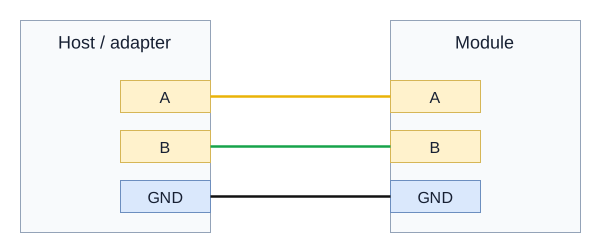
Wire colours: positive (+) red, negative (-) black, RS485 A yellow, and RS485 B green. Identify each connection by its terminal label.
DC Power
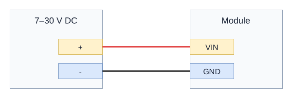
Connect 7-30 VDC to VIN and GND. Sensor supply voltage is determined by the sensor specification. V_out is unused and must not be used to power a sensor.
Voltage Input
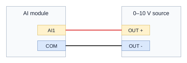
Use the ordered 0-10 V input version. Connect signal positive to AI1 and signal negative to COM. Power the sensor from a suitable separate source.
Current Input - Powered Source
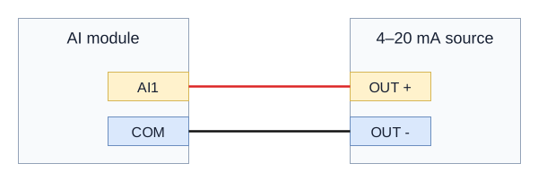
Use the ordered 4-20 mA input version. Connect the powered source's current output positive to AI1 and its signal return to COM. For a four-wire transmitter, its separate power pair is wired to the transmitter supply.
Current Input - Two-Wire Transmitter
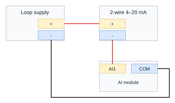
Connect loop supply positive to transmitter positive, transmitter negative to AI1, and COM to loop supply negative. Select the loop supply for the transmitter and input burden.
Three-Wire Sensor
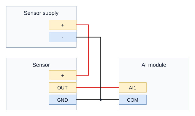
Connect sensor OUT to AI1. Connect sensor GND, sensor supply negative, and module COM together. Connect sensor supply positive to the sensor power input. Match voltage or current output to the ordered module input version.
Channel Notes
Repeat the circuit for each fitted AI channel. Terminal labels can use AI_1 instead of AI1. Use the signal return marked COM on the supplied input version; do not substitute a power or serial ground without its hardware definition. Select the physical voltage/current input version when ordering; these drawings do not establish a software range-change command.
Serial Wiring
Use the ordered RS485 or RS232 interface. On combined labels, TX/A+ is RS485 A or RS232 TX, and RX/B- is RS485 B or RS232 RX.
RS485
Connect A to A, B to B, and the signal reference to GND. Use twisted pair and a line topology. Add 120-ohm termination at the two physical ends when required by bus length and speed.
RS232
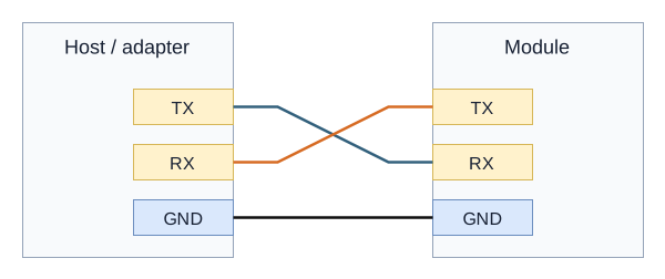
Connect host TX to module RX, host RX to module TX, and GND to GND. A USB-to-RS232 adapter is required for an RS232 module; a TTL adapter is unsuitable.
Commissioning
- Check power voltage, polarity, signal range, and terminal labels with power off.
- Apply module power and check the power indicator.
- Match the host serial settings and device address to the supplied configuration.
- Test one channel with a known signal or receiver before connecting the remaining channels.
- Confirm values or output setpoints using the communication instructions in the specification.
- Manufacturer: Hunan YenGear Tech Co., Ltd.
- Email: [email protected]
- Website: www.yengear.com