
Appearance
Y406-22/44/66/88/GG-L LoRa Wireless Controller Specification
| Y406-44-L Controller | Y406T-44-L Handheld Remote |
|---|---|
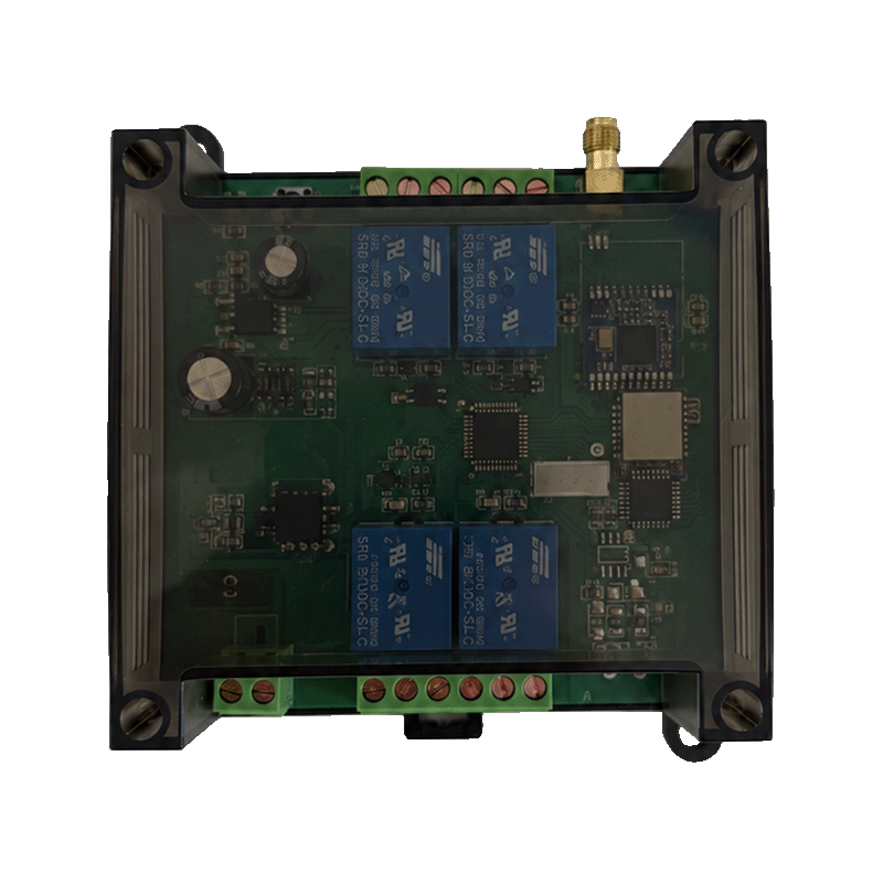 | 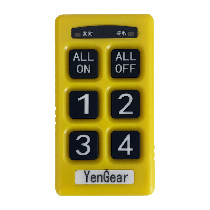 |
Contents
- Overview
- Ordering Information
- Key Features
- Technical Specifications
- Interfaces and Indicators
- Mechanical and Environmental
- Installation and Wiring
- Important Notes
1. Overview
Y406 is a LoRa wireless controller series for handheld operation of relay-controlled equipment. It offers 2, 4, 6, 8, or 16 control circuits for applications such as pumps, fans, lighting, and valves. RS485 is an operational control interface, not a configuration-only port.
For PLC integration, a separate communication expansion board reports remote-key states over Modbus RTU. Its register map is not yet verified for the Y406 relay controllers.
2. Ordering Information
2.1 Model Selection
| Model | Control circuits | Intended DI / DO count |
|---|---|---|
| Y406-22-L | 2 | 2 / 2 |
| Y406-44-L | 4 | 4 / 4 |
| Y406-66-L | 6 | 6 / 6 |
| Y406-88-L | 8 | 8 / 8 |
| Y406-GG-L | 16 | 16 / 16 |
In Y406-XX-L, the two code positions represent DI / DO counts; each G means 16, and L means LoRa. The code alone does not identify physical DI terminals. The terminal diagram must distinguish local inputs from remote-key or PLC mappings.
2.2 Power and Remote Selection
Choose one power version: 12 V DC, 24 V DC, or 220 V AC. Include the controller model and voltage in the order. These are separate versions, not a universal-input rating.
Order the remote model, key layout, antenna, and accessories with the controller. Custom key labels identify the operator's actions; PLC programming determines their function in the PLC control path. Labels such as ALL ON and ALL OFF are not Modbus commands. LCD feedback requires a compatible remote and feedback protocol.
3. Key Features
- Handheld LoRa operation for relay-controlled equipment.
- Local relay contacts for load switching; ratings and terminal assignments are not specified.
- RS485 key-state access through the PLC expansion-board protocol.
- Pairing and single-key/multi-key modes on the reference board, with up to 10 learned remotes per module; applicability to the controller firmware remains unverified.
- No Bluetooth or phone-app configuration.
4. Technical Specifications
4.1 Wireless
| Parameter | Specification |
|---|---|
| Wireless technology | LoRa |
| Operating frequency | 433 MHz reference specification; check the ordered radio version |
| Receiver sensitivity | < -115 dB in the source; measurement unit and test conditions not specified |
| Antenna | External antenna; connector and antenna specifications not specified |
| Range, transmit power, and air-data rate | Not specified |
The sensitivity value is not a verified rating in dBm.
4.2 Electrical and I/O
| Parameter | Specification |
|---|---|
| Complete-controller power versions | 12 V DC / 24 V DC / 220 V AC, selected when ordering |
| Reference PLC expansion-board supply | 5–30 V DC; not a complete-controller input rating |
| Control circuits | 2 / 4 / 6 / 8 / 16, depending on model |
| Physical DI terminals and input type | Not specified; use the model-specific terminal diagram |
| Local relay outputs | Relay contacts; ratings and terminal assignments not specified |
| Current and power consumption | Not specified |
| Power-cycle output retention | Not specified |
4.3 RS485 Communication Reference
The PLC expansion-board protocol uses these settings. Controller-specific defaults and register compatibility remain unverified.
| Parameter | Reference value |
|---|---|
| Protocol | Modbus RTU |
| PLC / module roles | Master / slave |
| Default slave address | 1 (0x01) |
| Default serial format | 9600 bit/s, 8 data bits, no parity, 1 stop bit (8N1) |
| Documented function | 0x03 — Read Holding Registers |
| Demonstrated register / quantity | Wire address 0x0000 / 1 register |
| Register byte order | High byte first |
| CRC byte order | Low byte first |
Register 0x0000 contains keys 1–16 in bits 0–15. The Technical Manual contains the read frames and register details. Write commands for relay outputs, feedback, parameters, and reset are not specified.
5. Interfaces and Indicators
| Interface / indicator | Description |
|---|---|
| Power | Version-specific input terminals; follow the unit's wiring diagram |
| Relay contacts | Local load-switching contacts; pinout and contact ratings not specified |
| RS485 | A/B terminals on the 16-circuit reference controller; terminal position and functions on other versions need a model-specific drawing |
| Antenna | External antenna connection |
| Learn button | Pairing and key-mode control on the reference board |
| Remote TX / RX indicators | Transmit/receive indicators on Y406T-44-L; flash patterns not specified |
A remote acknowledgement reports communication with the module. It does not prove relay operation or equipment state.
6. Mechanical and Environmental
6.1 Dimensions
Dimensions use width × height × depth.
| Model | Controller dimensions (W × H × D) |
|---|---|
| Y406-22-L | 95 × 110 × 45 mm |
| Y406-44-L | 95 × 110 × 45 mm |
| Y406-66-L | 95 × 110 × 45 mm |
| Y406-88-L | 125 × 110 × 45 mm |
| Y406-GG-L | 180 × 100 × 50 mm |
| Other item | Dimensions / applicability |
|---|---|
| Red reference remote | 54 × 165 × 30 mm; does not specify the Y406T-44-L enclosure |
| Y406T-44-L remote | Dimensions not specified |
| Reference PLC expansion board | Approximately 54 × 43 × 82 mm; not a relay-controller enclosure |
6.2 Installation and Environment
| Parameter | Specification |
|---|---|
| Mounting method, hole spacing, and tolerances | Obtain the ordered model's production drawing |
| Weight and housing material | Not specified |
| Protection rating | Not specified |
| Operating/storage temperature and humidity | Not specified |
| Certifications | Not specified |
Allow access to the antenna connector and terminals. Use the production drawing for mounting holes and installation clearances.
7. Installation and Wiring
- Match the controller, remote, power version, and firmware to the order and terminal drawing.
- Wire power and relay loads according to the ordered unit's ratings. Never apply 220 V to the reference expansion board's 5–30 V DC input.
- Check RS485 polarity, grounding, termination, and biasing.
- Pair the remote and test one key or one documented command before connecting operational loads.
- Apply appropriate load switching, protection, and application interlocks.
- Test key release, wireless loss, RS485 loss, restart, and recovery before commissioning.
Use the Technical Manual for reference pairing steps, command examples, and the commissioning checklist.
8. Important Notes
- Do not use Y406 for safety-rated emergency stops or control that requires guaranteed timing.
- A valid RS485 response does not prove that the remote-key state is fresh. Verify wireless-loss and retained-state behavior separately.
- Do not apply the expansion-board register map to a relay controller without a compatible protocol sheet.
- Y406 does not include 4G, Wi-Fi, Ethernet, cloud services, or LoRaWAN gateway connectivity.