
Appearance
FANUC CNC Data Acquisition Gateway User Manual
The gateway reads FANUC CNC data through the machine's Ethernet interface and publishes it to an MQTT broker. Setup requires the CNC network address, communication port, and MQTT connection details.
The illustrated setup covers the Wi-Fi version. English menu names include the Chinese labels shown on the configuration interface. Firmware version and installed hardware determine the available options.
For version selection and supported data points, see the FANUC CNC Data Acquisition Gateway Datasheet. For 4G, OPC UA, or offline-storage setup, contact technical support for instructions specific to your gateway version.
Contents
- Before You Start
- Interfaces and Wiring
- Access the Configuration Interface
- Configure the Network
- Configure CNC Acquisition and MQTT Publishing
- Verify Communication and Data
- Recover LAN1 Access
- Troubleshooting
- Hardware Reference
1. Before You Start
Before installation, have these items ready:
- The gateway and a suitable 12-24 V DC power supply.
- A commissioning computer with an Ethernet interface and a browser, preferably Google Chrome.
- Ethernet cables for the computer, CNC, and factory network as required.
- The CNC Ethernet IP address, subnet mask, and enabled communication port. Use TCP port 8193 for this setup.
- An unused IP address for each gateway network interface and the factory-network gateway address where required.
- For Wi-Fi: the network name, password, and addressing requirements.
- For MQTT: broker address, port, client ID, and authentication details supplied by the platform administrator.
Confirm that the CNC controller supports the required Ethernet communication functions. Available data points depend on the controller and its configuration.
CNC restart
Changes to the CNC Ethernet IP address and port 8193 require a machine power-off and restart before communication testing. Follow the procedure in Section 6.1.
2. Interfaces and Wiring
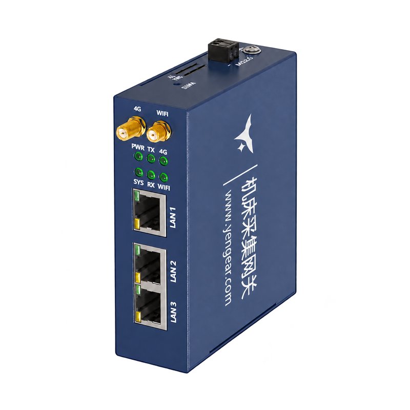
| Interface | Connection | Configuration interface |
|---|---|---|
| DC power | 12-24 V DC supply; follow the polarity markings on the device | Not applicable |
| LAN1 | Commissioning computer, factory switch, or server network | Network Card 1 (网卡1) |
| LAN2 | CNC Ethernet interface | Network Card 2 (网卡2) |
| LAN3 | Alternative CNC connection | Network Card 2 (网卡2), shared with LAN2 |
| Wi-Fi antenna | Antenna supplied for a Wi-Fi-equipped version | Wi-Fi Settings (WIFI设置) |
| RESET | LAN1 access recovery; see Section 7 | Physical button |
LAN2 and LAN3 form a two-port switch with one shared CNC-side IP address.
- With power disconnected, connect the DC supply according to the device markings.
- Connect the commissioning computer to LAN1.
- Connect the CNC Ethernet cable to LAN2 or LAN3.
- Connect the upstream factory network to LAN1 when required, or prepare the Wi-Fi connection.
- Apply power to the gateway.
3. Access the Configuration Interface
3.1 Factory Network Addresses
| Port | Factory IP address | Network card |
|---|---|---|
| LAN1 | 192.168.1.230 | Card 1 |
| LAN2 / LAN3 | 192.168.0.230 | Card 2 |
3.2 Set the Computer Address
Set the computer's Ethernet address to the LAN1 subnet. Example settings for a direct connection:
| Computer setting | Example |
|---|---|
| IP address | 192.168.1.100 |
| Subnet mask | 255.255.255.0 |
Use an unused address. Do not assign 192.168.1.230 to the computer because it conflicts with the gateway.
On Windows, open the Ethernet adapter's IPv4 properties and enter the address and subnet mask. If you plan to move LAN1 to the factory subnet, add an unused address from that subnet under Advanced. The computer then has an address for each subnet during setup.
3.3 Open the Gateway Page
- Confirm that the computer is connected to LAN1 and the gateway is powered.
- Enter
http://192.168.1.230in the browser. - Wait for the configuration interface to load.
If the interface requests a username and password, use the credentials supplied with the device.
4. Configure the Network
4.1 LAN1: Factory Network
- Open Network Settings (
网络设置) > Wired Network Settings (有线网络设置). - Select Network Card 1 (
网卡1). - Enter the assigned LAN1 IP address, subnet mask, and gateway address.
- Click Save (
保存).
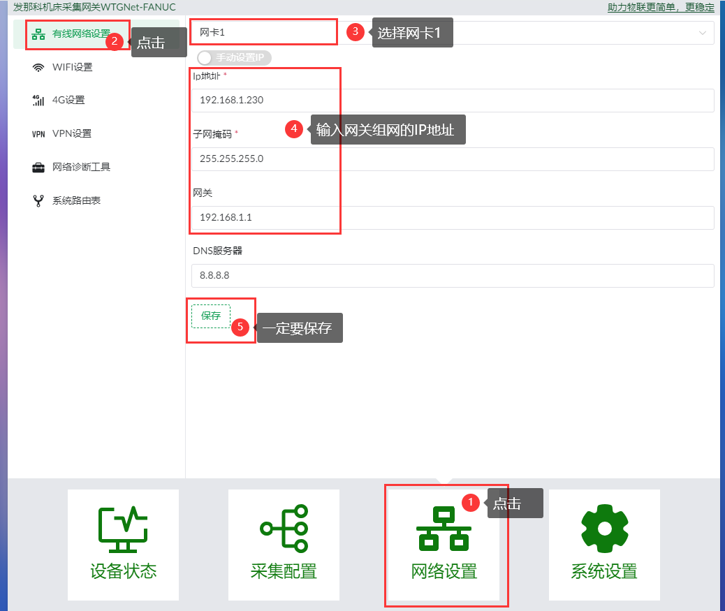
LAN1 uses the addressing plan of the factory or server network. Record the new address before restarting the gateway.
4.2 LAN2 / LAN3: CNC Network
- In Wired Network Settings, select Network Card 2 (
网卡2). - Assign an unused IP address in the same subnet as the CNC Ethernet interface.
- Enter the subnet mask and other network settings required by the installation.
- Click Save (
保存).
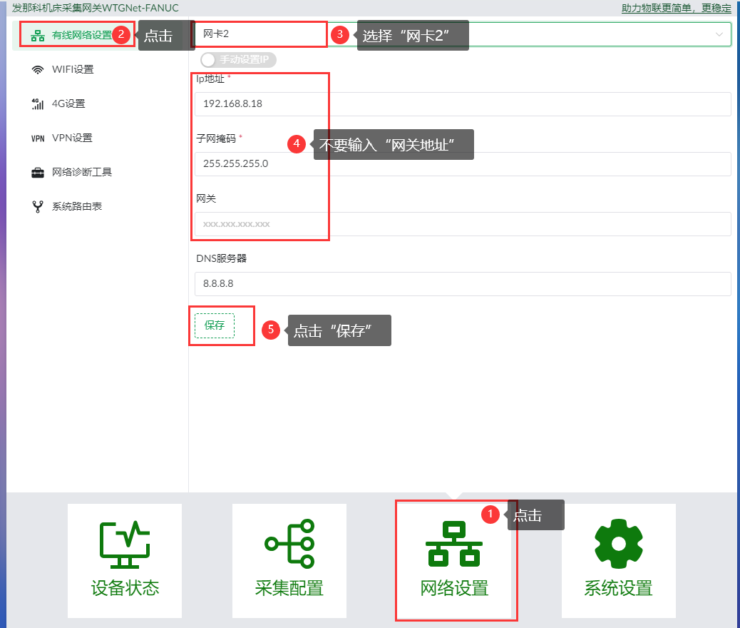
Example: for a CNC at 192.168.8.201 with subnet mask 255.255.255.0, assign the gateway an unused address such as 192.168.8.230. Use different addresses for the gateway and CNC.
Restart the gateway to apply the saved network-card settings.
4.3 Wi-Fi
For the Wi-Fi version:
- Open Network Settings (
网络设置) > Wi-Fi Settings (WIFI设置). - Enable Wi-Fi and click Scan Available Wi-Fi (
扫描可用WIFI). - Select the required network and enter its password.
- Switch from automatic IP addressing to manual settings.
- Enter an unused IP address and subnet mask for that Wi-Fi network.
- Enter the router/gateway address when required to reach the receiving platform outside the local subnet.
- Click Connect (
连接) and verify the connection.
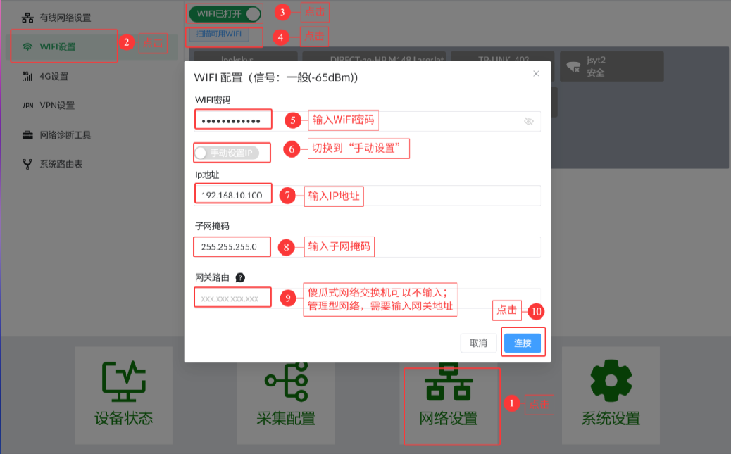
192.168.10.100 and 255.255.255.0 are example settings. Use the site's assigned address and subnet mask. A router/gateway address is optional for local LAN communication and required to reach networks beyond the local subnet.
4.4 Restart the Gateway
- Open System Settings (
系统设置) > System Settings (系统设置). - Select Restart Gateway (
重启网关) and execute the operation. - Allow approximately 25 seconds for the restart.
- Reopen the gateway at its configured LAN1 address. If the subnet changed, update the computer's Ethernet settings or use the additional address prepared earlier.
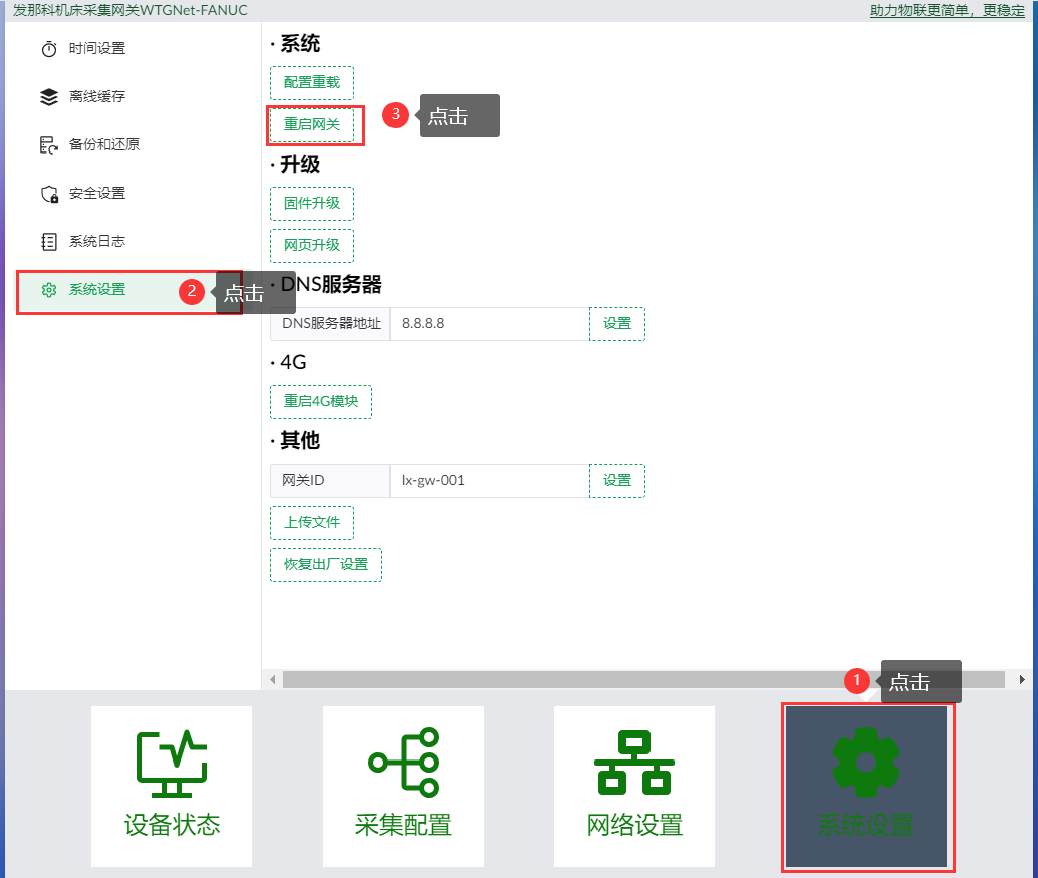
If the browser does not return to the configuration page, enter the current LAN1 address.
5. Configure CNC Acquisition and MQTT Publishing
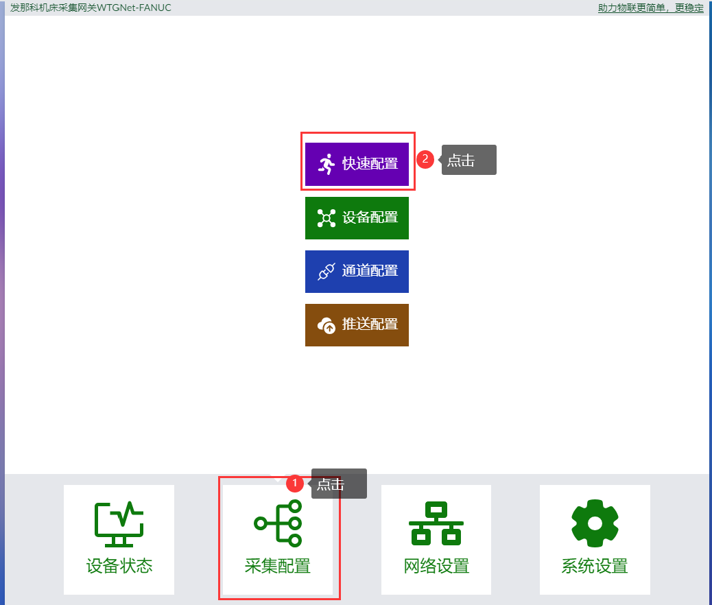
5.1 Start Quick Configuration
Open Acquisition Configuration (采集配置) > Quick Configuration (快速配置). The wizard creates the device, acquisition channel, and MQTT push configuration.
5.2 Enter the Machine Information
- Choose a Device Number (
设备编号) for the CNC. You cannot change this identifier later. - Enter the Device IP (
设备IP), using the actual CNC Ethernet address. - Click Next (
下一步).
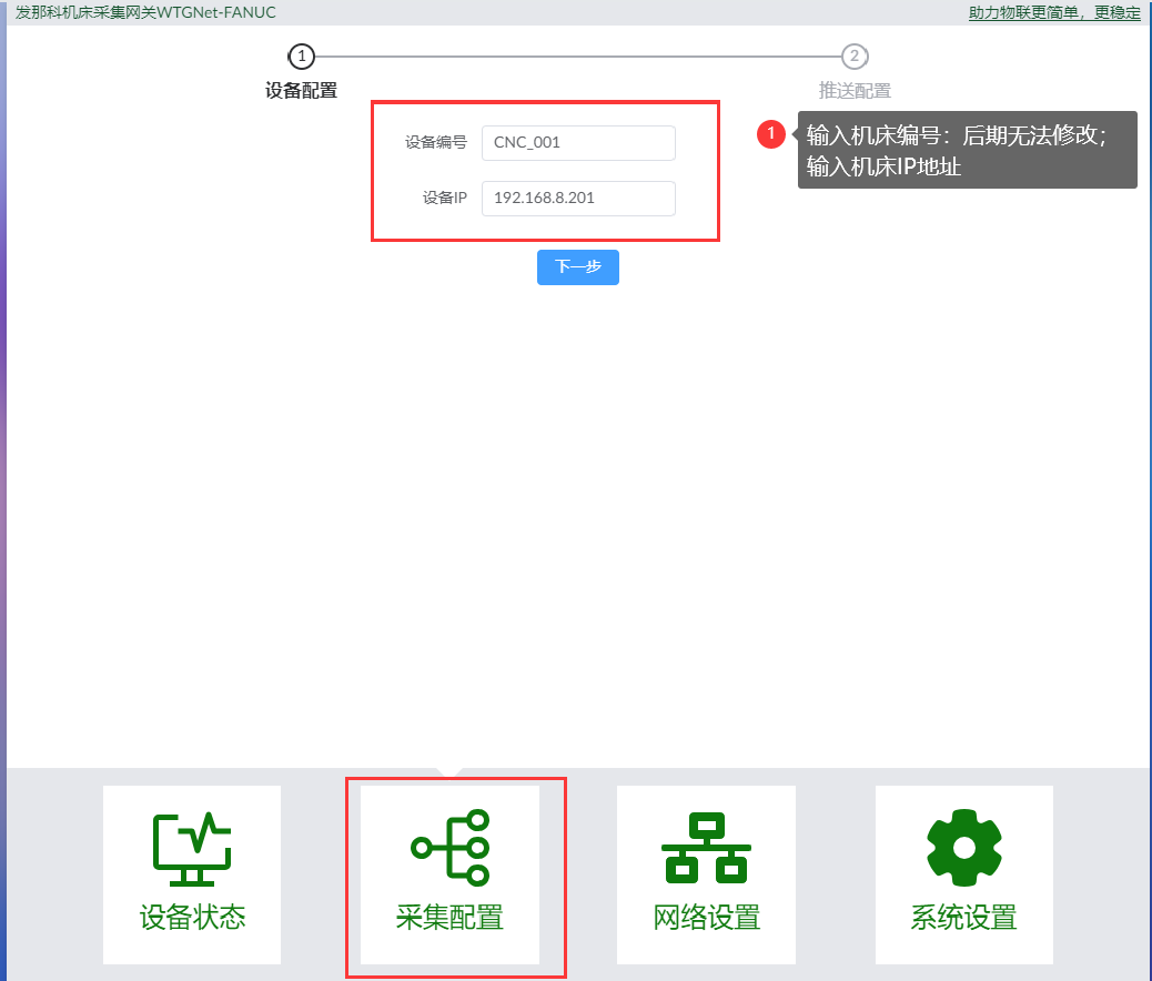
Example device number: CNC_001. Example CNC address: 192.168.8.201.
5.3 Enter the MQTT Broker Information
Select MQTT as the push method and enter the platform's connection parameters.
| Field | What to enter |
|---|---|
Server address (服务器地址) | The MQTT broker address |
Port (端口号) | The broker's configured listener port; example: 1883 |
Client ID (客户端ID) | An ID accepted by the broker and unique among active clients; the interface provides a Random (随机) button |
Username (用户名) | Broker username, if required |
Password (密码) | Broker password, if required |
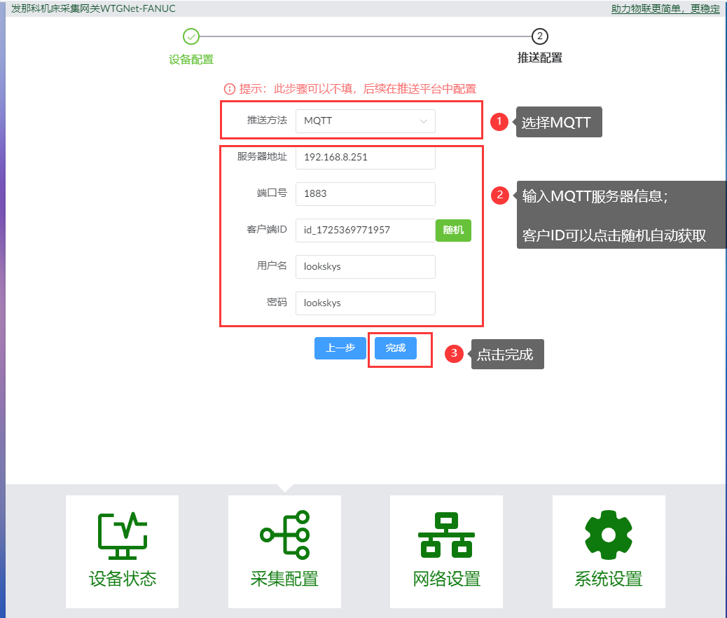
Use the broker address and credentials supplied by your platform administrator. The values in the image are examples.
Click Finish (完成) and confirm the prompt. After approximately 10 seconds, the detailed configuration page opens. If the broker details are not yet available, leave the push fields blank and complete them later in Push Configuration.
5.4 Review Device Settings and Data Points
Review the generated device configuration:
| Setting | Check |
|---|---|
| Device number | Correct machine identifier |
| Device name and description | Machine name and description |
| Acquisition channel | Channel associated with this CNC |
| Device model | Fanuc CNC 通用 (General FANUC CNC) for this setup |
Acquisition period (采集周期) | Polling interval suitable for the controller and application |
| Push configuration | Correct MQTT connection |
Push topic (推送主题) | Topic expected by the receiving application |
| Data points | Required points supported by the connected CNC |
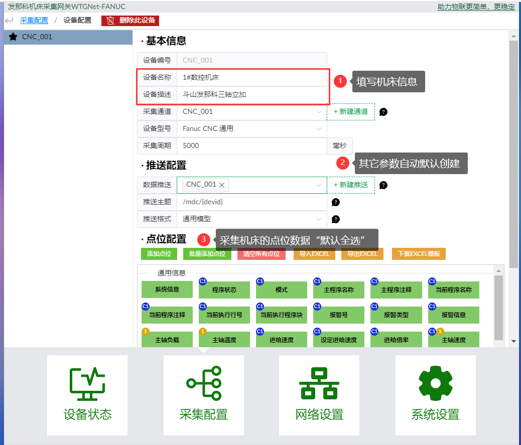
Example settings: acquisition period 5000 ms, push topic /mdc/{devid}. Set the period for the required update rate. Verify the resulting topic and message format at the receiving platform before using the data.
The wizard selects all machine data points by default. Keep the points needed for the application and supported by the CNC. Add points individually or in batches, or use the Excel import/export controls. For an import, download the template from the gateway and follow its column format.
5.5 Submit and Save
- Scroll to the bottom of the detailed configuration pane.
- Click Submit and Save Configuration (
提交和保存配置). - Wait for the gateway to reload the configuration.
- Review the automatically created Device Configuration (
设备配置), Channel Configuration (通道配置), and Push Configuration (推送配置).
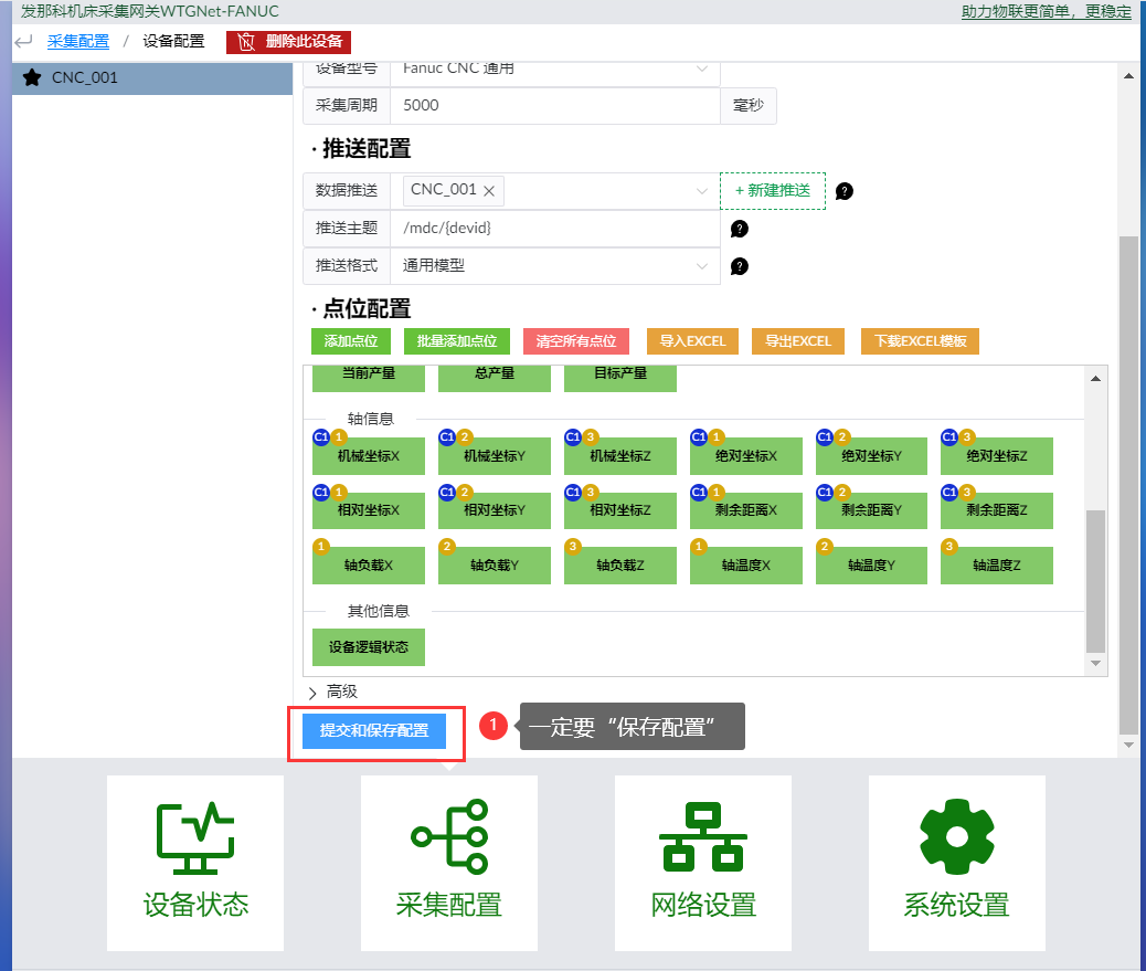
Save from this page even if you have already clicked Finish in the wizard.
5.6 Check the Acquisition Channel
Open Channel Configuration and select the generated CNC channel.
| Setting | Value |
|---|---|
| Channel type | TCP communication (TCP通信) |
| IP address | Actual CNC Ethernet IP address |
| Port | 8193, matching the configured CNC communication port |
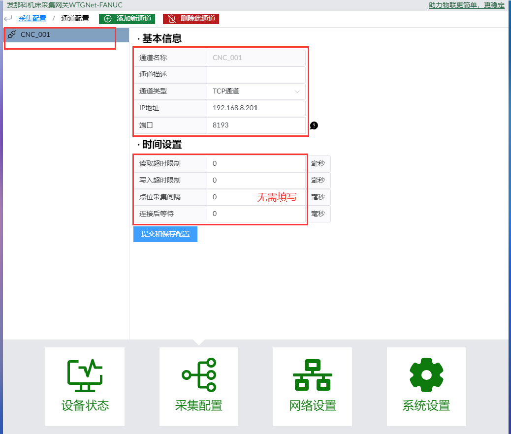
Leave the generated read/write timeout, point-acquisition interval, and connection timing settings unchanged unless the firmware instructions specify otherwise. The example uses 0 for these fields; do not interpret this value as disabling timeouts or delays.
Save any changes with Submit and Save Configuration (提交和保存配置).
5.7 Check the Push Configuration
Open Push Configuration and select the generated MQTT connection. Check the broker address, port, client ID, username, and password, then save any changes.
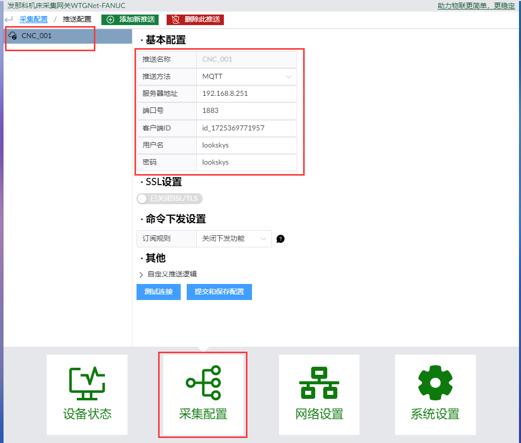
Click Test Connection (测试连接) to test access to the MQTT broker.
For SSL/TLS or command subscriptions, obtain the certificate and command-handling instructions for the installed firmware before enabling these options.
6. Verify Communication and Data
6.1 Restart the CNC After Network Changes
After setting the CNC IP address and port 8193, ask authorized machine personnel to shut down, power off, and restart the CNC according to its operating procedure. Complete the restart before running the network tests.
6.2 Test the CNC IP Address and Port
- Open Network Settings (
网络设置) > Network Diagnostic Tools (网络诊断工具). - Enter the CNC IP address in the PING field and click Execute (
执行). - In the port test, enter the same CNC IP address and port 8193.
- Click Execute (
执行) and review the result.
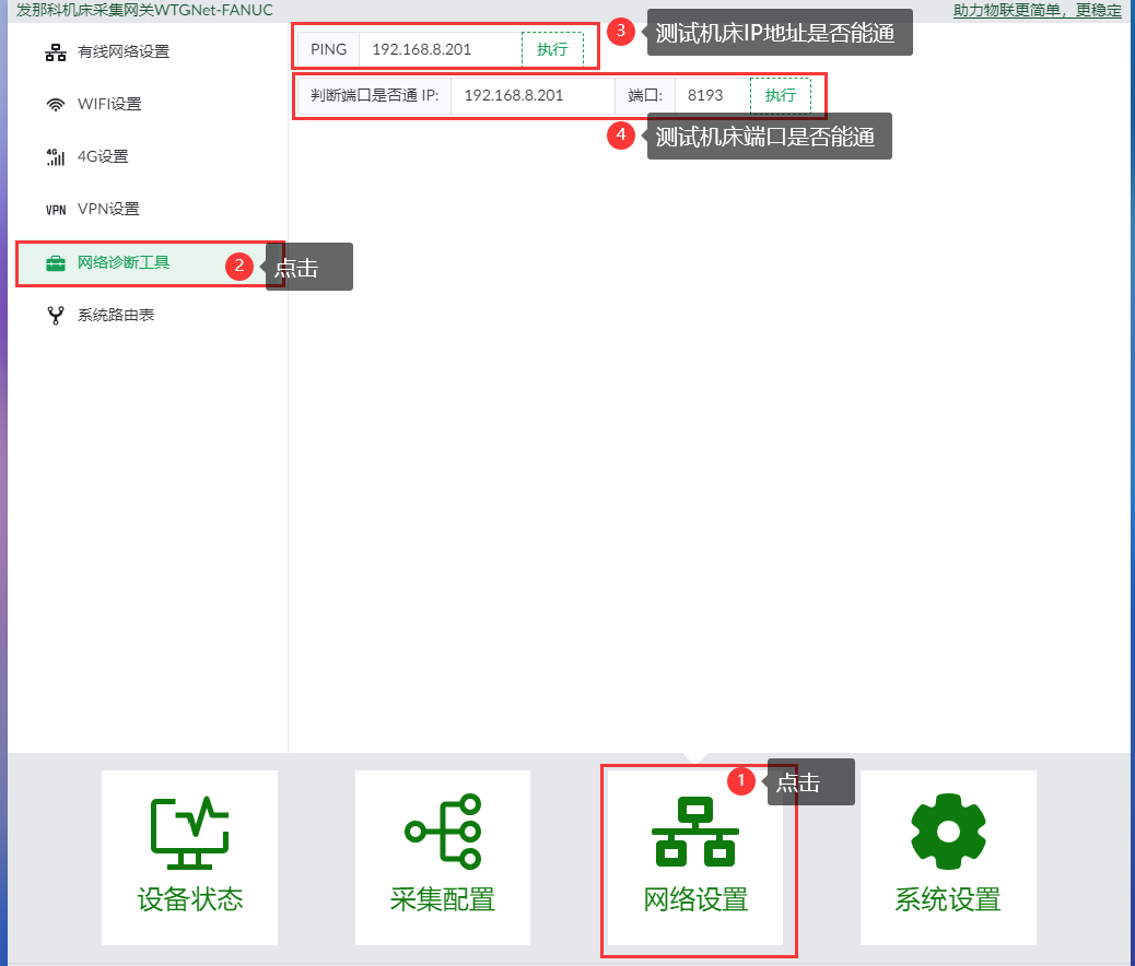
A successful PING shows IP reachability. A successful port test shows access to the communication port. Verify the acquired values separately against the CNC display.
6.3 Verify Acquisition and MQTT Delivery
After the network tests succeed:
- Open Device Status (
设备状态) and check the connected machine's reported data. - Compare selected values with the CNC display. Confirm units, scaling, and update intervals for the points used by the application.
- Verify the MQTT connection as described in Section 5.7.
- At the receiving platform, verify that messages arrive on the configured topic and belong to the correct device.
- Compare the payload with the JSON Data Reference, then check that updates follow the configured acquisition behavior.
- Record the final network addresses, CNC port, device number, selected points, acquisition period, broker details, and topic. Keep passwords in the site's approved credential store.
For QoS, retained messages, or offline buffering, verify the settings and behavior required by the receiving application with technical support before commissioning.
7. Recover LAN1 Access
If the configured LAN1 address is unknown or inaccessible:
- With the gateway powered, press and hold the top RESET button for more than 10 seconds.
- Connect the computer to LAN1 and give it an unused address in the
192.168.1.xsubnet, as described in Section 3. - Open
http://192.168.1.230and check access.
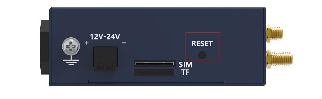
RESET restores LAN1 access at 192.168.1.230. Its effect on acquisition, MQTT, Wi-Fi, and other settings is unspecified. Record accessible settings before pressing RESET, then review the configuration afterward.
8. Troubleshooting
| Symptom | Checks and action |
|---|---|
| Configuration page does not open | Check power and the LAN1 cable. Verify that the computer and LAN1 are in the same subnet and have different IP addresses. Use the current LAN1 address. |
| Access is lost after changing LAN1 | Restart the gateway to apply the saved settings, adjust the computer's subnet, and open the new LAN1 address. |
| CNC IP test fails | Check the CNC-side cable, machine power, Card 2 address, subnet mask, and duplicate addresses. LAN2 and LAN3 share Card 2 settings. |
| CNC IP is reachable but port test fails | Check that the CNC communication port is enabled and matches the channel port. Confirm that the required full CNC power-off/restart was completed. |
| Network tests pass but data is missing | Check the selected channel, device model, and data points. Confirm that the controller provides the required communication functions and values. |
| MQTT connection test fails | Check upstream connectivity, broker address and port, credentials, and client ID. Check the network gateway address when the broker is outside the local subnet. |
| MQTT connects but the platform receives no usable data | Check acquisition status, the device's push association and topic, the platform subscription, and payload expectations. |
| Wi-Fi does not connect | Check Wi-Fi enablement, selected network, password, antenna connection, and IP/subnet/gateway settings. |
| Configuration appears not to take effect | Complete Submit and Save Configuration and wait for the reload. Restart the gateway after network-card IP changes. |
| LAN1 address is unknown | Follow Section 7, then review the resulting settings. |
For support, provide the supplied gateway version, firmware version if available, FANUC controller details, network layout, diagnostic results, and relevant configuration screenshots. Remove passwords from screenshots.
9. Hardware Reference
| Parameter | Specification |
|---|---|
| Supply voltage | 12-24 V DC |
| Average supply current | Approximately 300 mA at 12 V DC |
| Ethernet | Three 100 Mbps ports; LAN1 independent, LAN2/LAN3 switch function |
| Other interfaces | One 2-pin power terminal, RESET button, grounding stud, TF slot, SIM slot, six indicators; antenna connections depend on version |
| Dimensions | 100 × 82 × 30 mm (L × W × H), excluding the power-cable interface and bracket |
| Operating temperature | -10 to +70 °C |
| Storage temperature | -40 to +85 °C |
| Relative humidity | Below 95%, non-condensing |
Confirm the supplied hardware rating
The operating temperature above is -10 to +70 °C; the companion datasheet lists -20 to +85 °C. Contact YenGear to confirm the rating for your gateway before selecting the installation environment.
YenGear · www.yengear.com · [email protected]