
Appearance
Y406-22/44/66/88/GG-L LoRa Wireless Controller User Manual
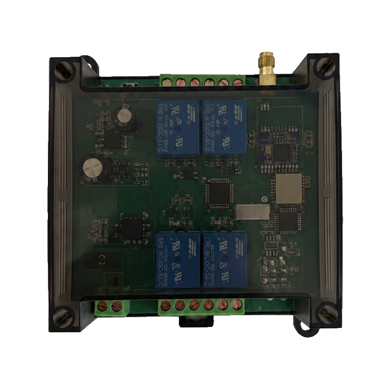
Applicable models: Y406-22-L, Y406-44-L, Y406-66-L, Y406-88-L, and Y406-GG-L. All models use a 9–72 V DC supply. See the Specification for model selection, power supply, and dimensions.
- Remote Configurator — configuration tool for compatible handheld remote setups.
Contents
- Product Introduction
- Installation and Wiring
- Remote Operation
- RS485 / Modbus RTU PLC Communication
- Commissioning
- Troubleshooting
- Safety and Maintenance
1. Product Introduction
Y406 uses a handheld remote to operate a controller over LoRa. The controller provides relay contacts for equipment control. Use the key labels and configuration supplied with the controller to identify the action of each key.
RS485 provides an operational communication interface for PLC integration. The Modbus RTU key-state protocol is described in section 4.
2. Installation and Wiring
2.1 Before Installation
- Check the controller model against the order and the unit's label. Confirm that the DC supply is within 9–72 V DC.
- Use the terminal drawing supplied for the controller. Terminal assignments depend on the model.
- Check the load voltage and current against the unit's relay contact ratings before connecting equipment.
- Disconnect the controller and load supplies before wiring.
2.2 Antenna and Mounting
Connect the external antenna and leave access to the antenna connector and wiring terminals. Keep the antenna clear of large metal surfaces. Use the controller's mounting drawing for hole positions and installation clearances.
2.3 Power Supply
Connect a 9–72 V DC supply to the terminals shown on the unit's wiring diagram. All Y406 controller models use this DC input range.
Check polarity before applying power.
2.4 Relay Connections
Connect the equipment control circuit according to the controller's terminal drawing and contact ratings. Select protection and any external switching devices for the load. Keep operational loads isolated while checking wiring and remote operation.
3. Remote Operation
3.1 Check the Remote
Use the remote supplied for the controller. Check the key labels against the equipment each key will operate. If the remote does not control the module, follow the pairing instructions supplied with that controller or contact technical support with the controller and remote models.
3.2 Operate the Equipment
- Make sure the equipment can be operated safely and the area is clear.
- Press one key and check the corresponding controller output and equipment action.
- Release the key and check the resulting action against the supplied key configuration.
- Repeat for each active key before normal use.
Use ALL ON or ALL OFF keys only after checking which equipment they affect. Key labels identify operator actions; the supplied configuration determines the output behavior.
The TX and RX indicators on Y406T-44-L show transmit/receive activity. Communication activity alone does not confirm that a relay has switched or that equipment has operated; check the equipment directly.
3.3 Remote Configuration
Use Remote Configurator to configure the handheld remote through a compatible BLE configuration module and firmware. Confirm compatibility with the supplied remote and configuration module before writing settings.
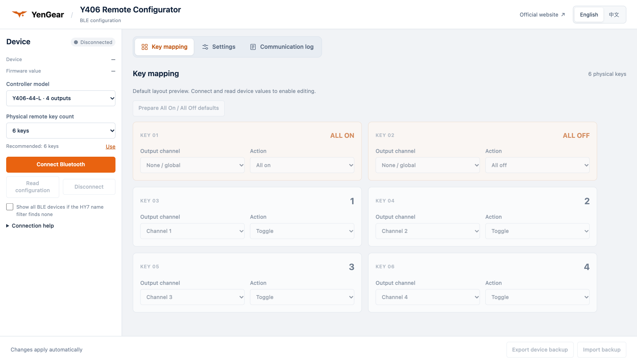
- Open Remote Configurator in desktop Chrome over HTTPS on a computer with Bluetooth enabled. Disconnect other configuration apps from the device.
- Select the controller model and the physical remote key count to match the supplied equipment.
- Choose Connect Bluetooth and select the compatible configuration device. The tool reads its current configuration after connecting.
- Review the current settings before changing key mappings or other supported parameters. Keep operational loads isolated while making configuration changes. Changes apply automatically after connecting and reading the device configuration.
- Wait for the save and readback confirmation, then check each key's action before returning the equipment to service. Use Export device backup to keep a copy of the configuration.
Use Read configuration to refresh the device settings. If disconnected, reconnect and read the configuration before writing again.
4. RS485 / Modbus RTU PLC Communication
In the PLC configuration, the PLC acts as the Modbus RTU master and reads remote key states from the communication module, which acts as a slave. The PLC program assigns equipment actions to those key states.
text
Handheld remote → LoRa → Communication module → RS485 / Modbus RTU → PLC logic → Equipment outputsThe parameters and frames below follow the manufacturer's RS485 Remote Communication Module PLC Expansion Board Manual, V1.00, dated 2024/09/02. Match them to the supplied module and firmware during commissioning; these transactions have not been tested on Y406 relay controllers.
4.1 RS485 Connection
Disconnect power before connecting RS485. Use the terminal drawing for the supplied controller to identify the A/B terminals and connect them to the corresponding terminals of the external device. Check polarity against both devices' drawings rather than relying on the letters alone.
Follow the installation requirements for grounding, termination, and biasing. Check the module's current address and serial settings before sending a request.
4.2 Communication Parameters
| Parameter | Manufacturer reference |
|---|---|
| Protocol | Modbus RTU |
| PLC / module roles | Master / slave |
| Default slave address | 1 (0x01) |
| Default baud rate | 9600 bit/s |
| Serial format | 8 data bits, no parity, 1 stop bit (8N1) |
| Documented read function | 0x03 — Read Holding Registers |
| Key-state read address / quantity | Wire address 0x0000 / 1 register |
| Register data byte order | High byte first |
| CRC byte order | Low byte first |
4.3 Register Map
Addresses and access labels below reproduce the manufacturer table. The worked read transaction uses wire address 0x0000; confirm wire addresses and commands for the other entries against the supplied firmware.
| Address as printed | Register | Listed access | Description / command status |
|---|---|---|---|
0 | Keys 1–16 | R/W | Bits 0–15 represent key states; 03 read example provided |
1 | Keys 1–16 | R/W | Same description as register 0; its separate purpose is not explained |
2 | PLC transmit signal | W | The description mentions 03 reading, which conflicts with W; operation and payload need clarification |
10000 | Communication address | R/W | Default 1; write command not provided |
10001 | Baud-rate selection | R/W | Selection codes below; write command not provided |
20000 | Factory reset | W | Table specifies writing 0; complete command not provided |
| Baud-rate code | Baud rate (bit/s) |
|---|---|
| 0 | 2400 |
| 1 | 4800 |
| 2 | 9600 — default |
| 3 | 19200 |
| 4 | 38400 |
| 5 | 57600 |
| 6 | 115200 |
The reference provides complete transactions for reading keys. R/W and W labels alone do not specify a write function code. Obtain the complete function code, address, payload, and response before changing parameters, sending PLC feedback, resetting the module, or controlling onboard relays.
4.4 Remote Key-State Mapping
The key-state word contains 16 bits. A set bit (1) means the corresponding key is pressed; a cleared bit (0) means it is released.
| Key | Bit | Mask | Key | Bit | Mask |
|---|---|---|---|---|---|
| 1 | 0 | 0x0001 | 9 | 8 | 0x0100 |
| 2 | 1 | 0x0002 | 10 | 9 | 0x0200 |
| 3 | 2 | 0x0004 | 11 | 10 | 0x0400 |
| 4 | 3 | 0x0008 | 12 | 11 | 0x0800 |
| 5 | 4 | 0x0010 | 13 | 12 | 0x1000 |
| 6 | 5 | 0x0020 | 14 | 13 | 0x2000 |
| 7 | 6 | 0x0040 | 15 | 14 | 0x4000 |
| 8 | 7 | 0x0080 | 16 | 15 | 0x8000 |
For example, 0x0005 has bits 0 and 2 set, so keys 1 and 3 are pressed. Use the key numbering supplied for the remote; the 16-bit protocol capacity does not define its physical key count or relay count.
The reference defaults to single-key mode: pressing several keys together stops command transmission. Reading simultaneous keys requires multi-key mode on both the remote and module. Stopped transmission is not a confirmed key-release report.
4.5 Read Request and Response Examples
All frames use hexadecimal bytes in transmission order. To read one key-state register at address 0 from slave 1, the PLC sends:
text
01 03 00 00 00 01 84 0A| Bytes | Meaning |
|---|---|
01 | Slave address 1 |
03 | Read Holding Registers |
00 00 | Starting wire address 0 |
00 01 | Read 1 register |
84 0A | CRC16, low byte first |
For PLC software using one-based or 4xxxx register labels, choose the setting that sends starting-address bytes 00 00. The request remains the same for each key state.
| Remote state | Complete response | Key-state word |
|---|---|---|
| No key pressed | 01 03 02 00 00 B8 44 | 0x0000 |
| Key 1 pressed | 01 03 02 00 01 79 84 | 0x0001 |
| Keys 1 and 3 pressed | 01 03 02 00 05 78 47 | 0x0005 |
In each normal response, 02 is the data-byte count. The following two bytes contain the key-state word, high byte first; the final two bytes contain the CRC. All four example frames have valid CRCs.
Validate the slave address, function code, byte count, frame length, and CRC before decoding the key states. Handle exception responses and timeouts separately. Let the PLC's Modbus library generate the request CRC, or calculate it with initial value 0xFFFF and reflected polynomial 0xA001.
4.6 PLC Logic and Feedback
The PLC program can use the key bits for hold-to-run, toggle, or separate start/stop logic. These are application logic choices: the 03 request reads keys and does not command an onboard relay. For toggle actions, detect a new key press rather than toggling on every poll, and initialize edge detection after startup or communication recovery.
The manufacturer describes module-receipt acknowledgement through the remote's receive indicator or buzzer. A compatible LCD remote can also display information sent by the PLC, but the reference does not provide a complete PLC-to-remote feedback command. Neither a key-state word nor a receipt acknowledgement confirms the equipment's actual state.
During commissioning, test key press, hold, release, wireless loss, and RS485 loss separately. A valid RS485 reply alone does not establish that the wireless key state is current. Define the PLC's timeout, output behavior on failure, and recovery behavior from the observed results.
5. Commissioning
- Check that the DC supply is within 9–72 V DC, then check polarity, wiring, antenna connection, and load ratings.
- With operational loads isolated, check each remote key and its corresponding relay contact action.
- Check both key press and release behavior, including any ALL ON or ALL OFF keys supplied.
- Reconnect the loads and test one equipment action at a time under controlled conditions.
- For PLC integration, match the settings to section 4 and the supplied protocol. Read and validate the key-state register, test each active key's press and release, and check the PLC output logic. Test simultaneous keys if required.
- Under safe test conditions, check remote power loss, communication loss, and controller power recovery. Check for unintended equipment startup before returning to normal operation.
6. Troubleshooting
| Symptom | Checks |
|---|---|
| Remote does not operate the controller | Check controller power, remote power, antenna connection, distance, obstructions, and remote compatibility. Follow the supplied pairing instructions. |
| Controller responds but equipment does not operate | Check the relay contact action, terminal wiring, load supply, and equipment protection devices. |
| A key operates unexpected equipment | Compare the key label, supplied configuration, and output wiring. Stop operation until the mapping is corrected. |
| RS485 communication fails | Check A/B wiring, communication settings, device address, and command compatibility against the supplied protocol. |
| Operation changes after a power interruption | Keep equipment in a safe state and check the unit's startup behavior before resuming use. |
If the problem continues, provide technical support with the controller model, actual DC supply voltage, remote model, wiring photograph, and a description of the fault. For an RS485 fault, also provide the communication settings and sent/received data.
7. Safety and Maintenance
- Do not use wireless operation as a safety-rated emergency stop or for control requiring guaranteed timing.
- Disconnect power before changing wiring or inspecting the controller.
- Keep the antenna and terminals secure, and inspect connections before returning equipment to service.
- Check actual equipment operation rather than relying only on remote indicators or communication responses.