
Appearance
Y406 LoRa Wireless Controller Technical Manual
| Y406-44-L Controller | Y406T-44-L Handheld Remote |
|---|---|
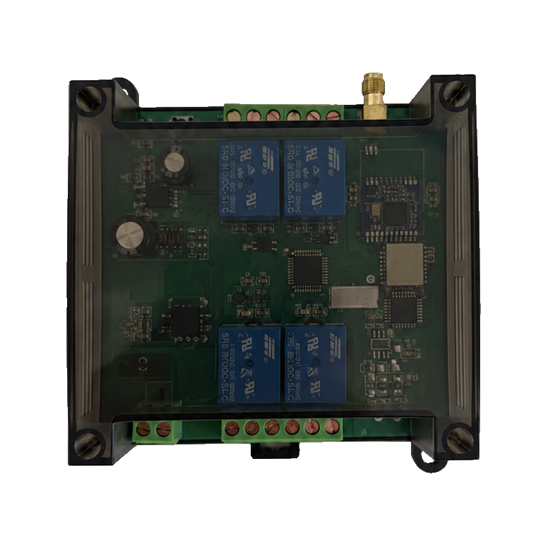 | 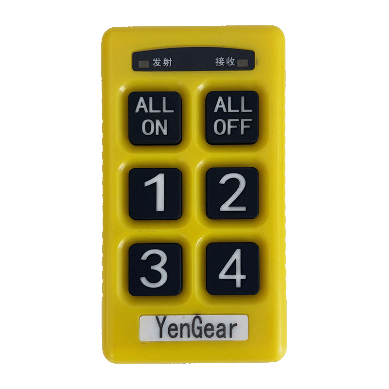 |
Models: Y406-22-L, Y406-44-L, Y406-66-L, Y406-88-L, and Y406-GG-L. See the Specification for model counts, dimensions, power versions, radio specifications, and product ratings.
Contents
- Overview
- Remote Pairing and Key Modes
- RS485 Communication
- PLC Control Examples
- Feedback and Communication Loss
- Commissioning Checklist
- Protocol Applicability
1. Overview
Y406 links a handheld remote to a controller over LoRa. In the PLC expansion-board configuration, the PLC reads key states over RS485 and assigns actions to its own outputs:
text
Remote key → LoRa → Communication expansion board → RS485 read → PLC logic → Cabinet relayThe relay controller and PLC expansion board are different hardware. The documented 03 command reads keys; it does not write an onboard relay. Controller-specific register compatibility and relay-write commands remain unverified.
1.1 Models
| Model | Control circuits | Intended DI / DO count |
|---|---|---|
| Y406-22-L | 2 | 2 / 2 |
| Y406-44-L | 4 | 4 / 4 |
| Y406-66-L | 6 | 6 / 6 |
| Y406-88-L | 8 | 8 / 8 |
| Y406-GG-L | 16 | 16 / 16 |
In Y406-XX-L, each G means 16 and L means LoRa. The code does not identify physical input terminals or a one-to-one key-to-output mapping. Use the ordered unit's terminal diagram and remote layout.
1.2 Product Parameters
Choose one power version when ordering. A 12 V DC, 24 V DC, or 220 V AC version does not accept all three supplies.
| Parameter | Specification |
|---|---|
| Wireless technology | LoRa |
| Operating frequency | 433 MHz reference specification; check the ordered radio version |
| Receiver sensitivity | < -115 dB in the source; measurement unit and test conditions not specified |
| Antenna | External antenna; connector and antenna specifications not specified |
| Range, transmit power, and air-data rate | Not specified |
| Parameter | Specification |
|---|---|
| Complete-controller power versions | 12 V DC / 24 V DC / 220 V AC, selected when ordering |
| Reference PLC expansion-board supply | 5–30 V DC; not a complete-controller input rating |
| Control circuits | 2 / 4 / 6 / 8 / 16, depending on model |
| Physical DI terminals and input type | Not specified; use the model-specific terminal diagram |
| Local relay outputs | Relay contacts; ratings and terminal assignments not specified |
| Current and power consumption | Not specified |
| Power-cycle output retention | Not specified |
1.3 Dimensions
Dimensions use width × height × depth.
| Model | Controller dimensions (W × H × D) |
|---|---|
| Y406-22-L | 95 × 110 × 45 mm |
| Y406-44-L | 95 × 110 × 45 mm |
| Y406-66-L | 95 × 110 × 45 mm |
| Y406-88-L | 125 × 110 × 45 mm |
| Y406-GG-L | 180 × 100 × 50 mm |
| Other item | Dimensions / applicability |
|---|---|
| Red reference remote | 54 × 165 × 30 mm; does not specify the Y406T-44-L enclosure |
| Y406T-44-L remote | Dimensions not specified |
| Reference PLC expansion board | Approximately 54 × 43 × 82 mm; not a relay-controller enclosure |
2. Remote Pairing and Key Modes
Pairing steps apply to the PLC expansion board and its compatible remote. The key combinations require the corresponding key layout and firmware.
2.1 Pair a Remote
Hold the module's learn button for approximately 5 seconds, then press the remote's top-left key. The reference module supports up to 10 learned remotes. Read individual key states through RS485 to test pairing.
2.2 Enable Simultaneous Keys
Both devices must use multi-key mode:
- On the remote, hold keys 1 and 6 for approximately 10 seconds until only the transmit indicator flashes. Release them, then press keys 1, 2, 3, and 4 in sequence.
- Power off the module. Hold its learn button, power it on, then release the button.
- Check individual keys, then verify that keys 1 and 3 together produce
0x0005.
Steps 1 and 2 toggle each device's single-key/multi-key setting. They do not explicitly select multi-key mode; repeating them may reverse the setting.
3. RS485 Communication
3.1 Connection and Default Settings
Wire RS485 from the module and PLC terminal diagrams. Check polarity: vendors do not necessarily use the same A/B labels. Follow the installation requirements for grounding, termination, and biasing.
| Parameter | Reference value |
|---|---|
| Protocol | Modbus RTU |
| PLC / module roles | Master / slave |
| Default slave address | 1 (0x01) |
| Default serial format | 9600 bit/s, 8 data bits, no parity, 1 stop bit (8N1) |
| Documented function | 0x03 — Read Holding Registers |
| Demonstrated register / quantity | Wire address 0x0000 / 1 register |
| Register byte order | High byte first |
| CRC byte order | Low byte first |
For PLC software with one-based or 4xxxx register labels, use the setting that transmits starting-address bytes 00 00.
The expansion board accepts 5–30 V DC. Do not wire a 220 V source to that input.
3.2 Register Map and Write-Command Status
The reference register map includes one complete transaction: reading register zero. R/W and W labels alone do not specify a write function code.
| Address as printed | Description | Listed access | Limitation |
|---|---|---|---|
0 | Keys 1–16, bits 0–15 | R/W | 03 read at wire address 0x0000 demonstrated; write method unspecified |
1 | Keys 1–16, bits 0–15 | R/W | Duplicates register 0's description; purpose unresolved |
2 | PLC transmit signal | W | Explanation mentions reading with 03, conflicting with W; direction and payload unresolved |
10000 | Communication address | R/W | Default 1; allowed range and write method unspecified |
10001 | Baud-rate selection | R/W | Codes below; write method unspecified |
20000 | Factory reset | W | Table says write 0; complete command unspecified |
Check the address radix and offsets before constructing requests for other entries. Register 1 does not identify a documented keys 17–32 bank.
| Baud-rate code | Baud rate (bit/s) |
|---|---|
| 0 | 2400 |
| 1 | 4800 |
| 2 | 9600 — default |
| 3 | 19200 |
| 4 | 38400 |
| 5 | 57600 |
| 6 | 115200 |
Write operations need a model-specific function code, wire address, payload, response, and change/reset behavior. Request working relay and feedback examples where supported. Do not substitute assumed 06 or 10 commands.
3.3 Key-State Bit Map
Bits 0–15 represent keys 1–16. A set bit means closed/pressed; a cleared bit means open/released.
| Key | Bit | Mask | Key | Bit | Mask |
|---|---|---|---|---|---|
| 1 | 0 | 0x0001 | 9 | 8 | 0x0100 |
| 2 | 1 | 0x0002 | 10 | 9 | 0x0200 |
| 3 | 2 | 0x0004 | 11 | 10 | 0x0400 |
| 4 | 3 | 0x0008 | 12 | 11 | 0x0800 |
| 5 | 4 | 0x0010 | 13 | 12 | 0x1000 |
| 6 | 5 | 0x0020 | 14 | 13 | 0x2000 |
| 7 | 6 | 0x0040 | 15 | 14 | 0x4000 |
| 8 | 7 | 0x0080 | 16 | 15 | 0x8000 |
For key number n, test (KeyWord AND (1 << (n - 1))) != 0. Restrict the program to active keys on the remote. The reference protocol reads one register regardless of circuit count.
3.4 Command Examples
Frames use hexadecimal bytes in transmission order. Spaces separate bytes for readability.
3.4.1 Read One Key-State Register
The PLC sends:
text
01 03 00 00 00 01 84 0A| Bytes | Meaning |
|---|---|
01 | Slave address 1 |
03 | Read Holding Registers |
00 00 | Starting address 0 |
00 01 | Quantity 1 |
84 0A | CRC, low byte then high byte |
The request does not change with the pressed key. The response contains the key-state word.
3.4.2 Manufacturer Response Examples
| Remote state | Complete response | Key-state word |
|---|---|---|
| No key pressed | 01 03 02 00 00 B8 44 | 0x0000 |
| Key 1 pressed | 01 03 02 00 01 79 84 | 0x0001 |
| Keys 1 and 3 pressed | 01 03 02 00 05 78 47 | 0x0005 |
02 is the data-byte count. The next two bytes are the register value: 00 05 means 0x0005, with bits 0 and 2 set.
Simultaneous keys require multi-key mode on both devices. In default single-key mode, pressing multiple keys stops transmission. Do not treat this as a key-release report.
3.4.3 Validate Before Decoding
Check the slave address, function, byte count, length, and CRC before accepting a normal response. Do not decode an exception response or incomplete frame as key data.
The CRC calculation uses initial value 0xFFFF and reflected polynomial 0xA001. Recalculate it whenever request bytes change, or let the PLC's Modbus library generate it. The four example frames have valid CRCs.
4. PLC Control Examples
The PLC program assigns key actions. Mapping bit 0 to a PLC output lets key 1 control cabinet relay 1; it does not write a module relay register.
The pseudocode assumes a validated sample and a current wireless state. Relay1Command is an application command, not a physical relay-state confirmation. Apply equipment interlocks and the chosen fault policy before driving an output.
4.1 Hold-to-Run
text
On a validated, current key-state sample:
    Key1 = (KeyWord AND 0x0001) != 0
    Relay1Command = Key1
Pressing key 1 requests ON; releasing it requests OFF. Test release reporting and wireless-loss behavior before using this mode.
4.2 Toggle on Each Press
text
On each validated, current sample:
    Key1 = (KeyWord AND 0x0001) != 0

    If this is the first sample after startup or communication recovery:
        PreviousKey1 = Key1
        Do not toggle
    Else:
        If Key1 is true and PreviousKey1 is false:
            Relay1Command = NOT Relay1Command
        PreviousKey1 = Key1
Toggle on a rising edge, not on every poll. Initializing the previous state prevents a held key from creating a false edge at startup or recovery. The fault policy must independently define what happens to the existing output command.
4.3 Separate Start and Stop Keys
text
On each validated, current sample:
    Key1 = (KeyWord AND 0x0001) != 0
    Key2 = (KeyWord AND 0x0002) != 0
    StartEdge = false

    If this is not the first sample after startup or communication recovery:
        StartEdge = Key1 AND NOT PreviousKey1

    If Key2 is true:
        Relay1Command = OFF
    Else if StartEdge is true and start interlocks permit:
        Relay1Command = ON

    PreviousKey1 = Key1
Key 2 has stop priority. Updating PreviousKey1 on every accepted sample avoids retaining an old start edge while stop is pressed. Use multi-key mode for simultaneous start/stop inputs. This wireless stop is not a safety-rated emergency stop.
5. Feedback and Communication Loss
A remote acknowledgement reports receipt at the module, not relay operation or equipment state. LCD feedback requires a compatible remote; the reference material does not specify a complete write protocol.
An RS485 reply does not establish wireless freshness. Test these behaviors before using key data for control:
- Key-release reporting and how long the module retains a key state.
- Register behavior after remote power loss or wireless-link loss.
- Any available wireless-link status or freshness indicator.
- A tested PLC polling interval, timeout, and output fault policy.
- Startup and recovery behavior for the PLC, module, and remote.
Test wireless loss separately from RS485 loss. No guaranteed latency, polling interval, or freshness timeout is specified.
6. Commissioning Checklist
- Match the hardware, firmware, terminal diagram, and power version to the order. Check protocol compatibility.
- Pair the remote. For the documented default setup, use slave 1, 9600 baud, and 8N1.
- Send
01 03 00 00 00 01 84 0A; validate the reply before decoding it. - Test every active key's press, hold, release, and rapid operation.
- Test simultaneous keys with both devices in multi-key mode, if required.
- Map key bits to PLC output tags; test interlocks with loads isolated where appropriate.
- Test wireless loss, RS485 loss, power loss, and retained key values independently.
- Test startup and recovery for unintended start or toggle actions.
- Obtain and test the missing write protocol before enabling direct relay writes, feedback, or parameter changes.
7. Protocol Applicability
The read protocol applies to the PLC expansion-board reference, V1.00, dated 2024/09/02. CRC checks validate the example bytes, not Y406 hardware compatibility. The read transactions have not been tested on Y406 relay controllers.
The PLC examples describe application logic, not built-in controller behavior. Complete write transactions and model-specific fault behavior are not specified. Use the ordered controller's firmware and protocol sheet for driver implementation.