
Appearance
Y406-22/44/66/88/GG-L LoRa Wireless Controller Specification
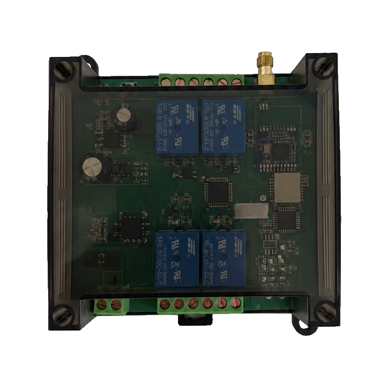
Contents
- Overview
- Ordering Information
- Key Features
- Technical Specifications
- Interfaces and Indicators
- Dimensions and Mounting
- Installation and Wiring
- Important Notes
1. Overview
Y406 is a LoRa wireless controller series for handheld operation of relay-controlled equipment. It offers 2, 4, 6, 8, or 16 control circuits for applications such as pumps, fans, lighting, and valves. RS485 provides an operational communication interface.
2. Ordering Information
2.1 Model Selection
| Model | Control circuits | DI / DO model code |
|---|---|---|
| Y406-22-L | 2 | 2 / 2 |
| Y406-44-L | 4 | 4 / 4 |
| Y406-66-L | 6 | 6 / 6 |
| Y406-88-L | 8 | 8 / 8 |
| Y406-GG-L | 16 | 16 / 16 |
In Y406-XX-L, the two code positions represent DI / DO counts; each G means 16, and L means LoRa. Use the supplied terminal diagram for physical input and output connections.
2.2 Power Supply and Remote Selection
Select a 9–72 V DC supply and follow the polarity markings on the supplied wiring diagram. Include the controller model in the order.
Order the remote model, key layout, antenna, and accessories with the controller. Custom key labels identify the operator's actions; use the key configuration supplied with the controller.
3. Key Features
- Handheld LoRa operation for relay-controlled equipment.
- Local relay contacts for load switching.
- Modbus RTU key-state reads over RS485 with compatible PLC expansion-board firmware.
- Handheld remote setup through Remote Configurator requires a compatible BLE configuration module and firmware.
4. Technical Specifications
4.1 Wireless
| Parameter | Specification |
|---|---|
| Wireless technology | LoRa |
| Operating frequency | 433 MHz reference radio version; use the frequency specified for the ordered unit |
| Antenna | External antenna |
4.2 Electrical and I/O
| Parameter | Specification |
|---|---|
| Controller power supply | 9–72 V DC |
| Control circuits | 2 / 4 / 6 / 8 / 16, depending on model |
| Local relay outputs | Relay contacts rated at 10 A / 250 V AC |
For PLC communication parameters, register mapping, and complete Modbus RTU read examples, see the User Manual.
5. Interfaces and Indicators
| Interface / indicator | Description |
|---|---|
| Power | 9–72 V DC input; follow the unit's wiring diagram and polarity markings |
| Relay contacts | 10 A / 250 V AC; follow the unit's wiring diagram |
| RS485 | Use the supplied model's terminal drawing for A/B connections |
| Antenna | External antenna connection |
| Remote TX / RX indicators | Transmit/receive indicators on Y406T-44-L |
A remote acknowledgement means the module received the command. Verify relay and equipment operation directly.
6. Dimensions and Mounting
6.1 Dimensions
Dimensions use width × height × depth.
| Model | Controller dimensions (W × H × D) |
|---|---|
| Y406-22-L | 95 × 110 × 45 mm |
| Y406-44-L | 95 × 110 × 45 mm |
| Y406-66-L | 95 × 110 × 45 mm |
| Y406-88-L | 125 × 110 × 45 mm |
| Y406-GG-L | 180 × 100 × 50 mm |
6.2 Mounting
Allow access to the antenna connector and terminals. Use the production drawing for mounting holes and installation clearances.
7. Installation and Wiring
See the User Manual for antenna placement, power wiring, and relay connections.
8. Important Notes
- Do not use Y406 for safety-rated emergency stops or control that requires guaranteed timing.
- Check communication-loss and power-recovery behavior before operating equipment.
- Use the protocol supplied for the controller model and firmware for RS485 commands.
- Y406 does not include 4G, Wi-Fi, Ethernet, cloud services, or LoRaWAN gateway connectivity.