
Appearance
Y201 Serial Gateways User Manual
Applicable models: Y201-R, Y201-W, Y201-G, Y201-L, and Y201C.
Models and Power
| Model | Uplink | Module supply | Detailed documents |
|---|---|---|---|
| Y201-R | Ethernet | 5-36 VDC | Specification / Technical Manual |
| Y201-W | Wi-Fi | 5-36 VDC | Specification / Technical Manual |
| Y201-G | 4G | 9-36 VDC | Specification / Technical Manual |
| Y201-L | LoRa | 9-36 VDC | Specification / Technical Manual |
| Y201C | CAN | 5-36 VDC | Specification / Technical Manual |
Each model has one ordered serial interface: RS485, RS232, or TTL. Check the ordered interface before wiring; the combined TX/A and RX/B labels do not mean these interfaces can be connected together.
Wire colours: positive (+) red, negative (-) black, RS485 A yellow, and RS485 B green. Identify each connection by its terminal label.
DC Power Wiring
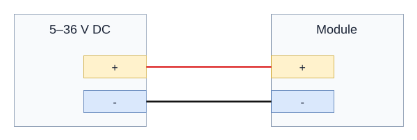
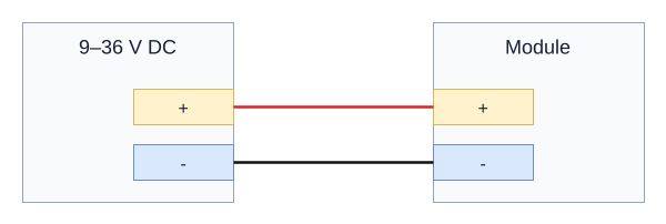
Power off before wiring. Connect supply positive to + and supply negative to -. Choose the supply range for the actual model. The drawings show electrical connections rather than connector pin order.
Y201-R / Y201-W / Y201C
Y201-G / Y201-L
RS485 Wiring
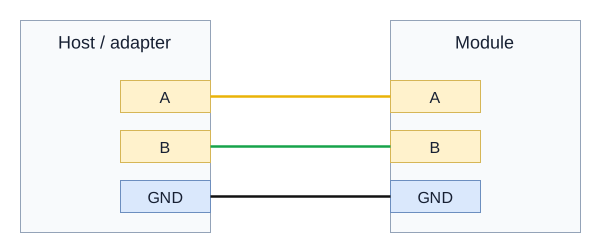
Connect A to A, B to B, and the serial signal reference to GND. On combined terminal labels, TX/A is A and RX/B is B. Use shielded twisted pair and a line topology, with 120-ohm termination at the two physical bus ends when required. Signal GND and chassis grounding are separate functions.
RS232 and TTL Wiring
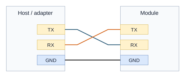
Connect host TX to module RX, host RX to module TX, and GND to GND. Use an adapter matching the fitted interface. Y201-R/W/L TTL variants use 3.3 V logic; confirm the fitted TTL level on Y201-G and Y201C before connecting. RS232 electrical levels must not be applied to TTL pins.
Y201C CAN Wiring
Connect CAN H to H, CAN L to L, and CAN signal ground to G. Keep both ends at the same CAN bit rate. Enable the module's built-in 120-ohm termination only if it is a physical CAN bus end; do not add a second resistor at that end when the built-in one is enabled.
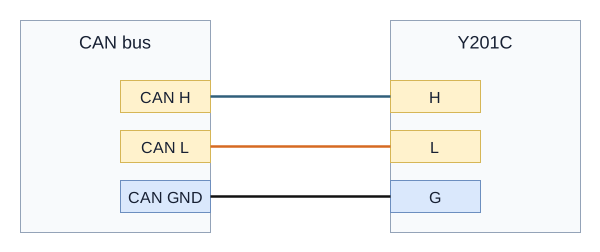
Y201C bridges CAN to its ordered serial interface. Its CAN and serial signal grounds must be connected according to their terminal labels. Y201C does not provide Ethernet.
Uplink Connections
| Model | Connection |
|---|---|
| Y201-R | Connect RJ45 to the Ethernet switch, router, or PC; supply DC power separately. |
| Y201-W | Fit the Wi-Fi antenna, then configure AP or STA operation as required. |
| Y201-G | With power off, insert the SIM and connect the 4G antenna before applying DC power. MicroUSB is for the documented maintenance functions. |
| Y201-L | Fit the LoRa antenna and match the peer's frequency, channel, and radio settings. |
| Y201C | Wire H/L/G, then match the CAN bit rate and serial transfer mode. |
First Communication Check
- Verify supply voltage, polarity, interface type, and terminal labels before power-on.
- Apply power and check the POWER indicator.
- Match serial baud rate, data bits, parity, and stop bits on both devices.
- Use the model's Technical Manual to configure its network, radio, or CAN link.
- Send known data in both directions and check the TX/RX or CAN activity indicators.
- Manufacturer: Hunan YenGear Tech Co., Ltd.
- Email: [email protected]
- Website: www.yengear.com