
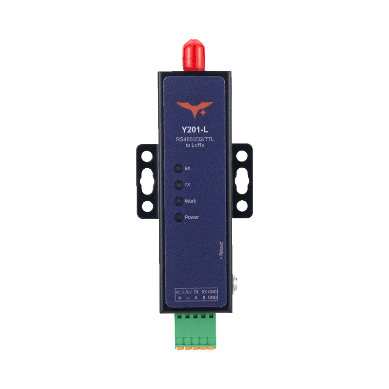
Appearance
Y201-L Technical Manual
Contents
- Overview
- Default Settings
- Serial Modes and Packetization
- LoRa Parameters and Communication Modes
- AT Command Conventions
- Common AT Commands
- Typical Configuration Flow
- Maintenance and Upgrade
- Troubleshooting
1. Overview
This manual explains configuration, commissioning, maintenance, and troubleshooting for the Y201-L mini LoRa DTU. It covers the serial AT command set, transparent and command modes, LoRa communication modes, relay networking, firmware upgrade, and parameter recovery.
| Item | Description |
|---|---|
| Frequency Band | 410 to 493 MHz |
| Serial Interface | Single-port RS232, RS485, or 3.3 V TTL, depending on the ordered variant |
| Communication Distance | Up to 5 km |
| Working Modes | Broadcast, fixed-point, master-slave, relay networking |
| Configuration Method | Serial AT commands |
2. Default Settings
| Parameter | Default |
|---|---|
| Serial Baud Rate | 115200 bps |
| Data Bits | 8 |
| Stop Bits | 1 |
| Parity | NONE |
| Serial Mode | Transparent mode |
| Hardware Flow Control | NFC |
| Base Frequency | 410 MHz |
| Step | 1 MHz |
| Channel | 20 |
| Speed Level | 5 |
| LoRa Mode | Broadcast mode, BRD |
| Retransmission Count | 0 |
| Retransmission Interval | 1000 ms |
| Relay | OFF |
| Relay Group ID | 0 |
| Relay Rule | 0,0 |
3. Serial Modes and Packetization
3.1 Serial Modes
Y201-L supports two serial working modes:
- Transparent Mode, default: Serial data is packetized and forwarded through LoRa
- AT Command Mode: Serial input is treated as AT commands and downlink data is not transparently forwarded
3.2 Entering AT Command Mode
Recommended sequence:
- Send
+++. - Wait longer than the packet interval and less than
3 s;500 msis recommended. - Send
a. - Enter AT mode only after receiving
+ok.
Notes:
- The device pauses data output for about
3 safter receiving+++ - Send AT queries and settings only after
+okis returned - AT mode is not saved across power cycles; the device returns to transparent mode after reboot
3.3 Exiting AT Mode
- Send
AT+EXIT\r\nand wait forOK. - Or reboot the device directly
3.4 Packetization
Serial data is transmitted when either condition is met:
- Length trigger: data length
>=packet length, default252, range5 to 252 - Interval trigger: inter-character gap
>=packet interval, default5 ms, range0 to 300 ms
4. LoRa Parameters and Communication Modes
4.1 Key Parameters
| Parameter | Meaning | Default |
|---|---|---|
Base Frequency, base | Frequency calculation baseline | 410 MHz |
Step, step | Frequency interval between adjacent channels | 1 MHz |
Channel, ch | Working channel number | 20 |
Speed, sp | LoRa speed level, 1 to 9; higher speed shortens the relative transmission distance | 5 |
Key, key | LoRa encryption string, 1 to 16 characters; write-only | No default |
Device Address, id | Local address in fixed-point or master-slave mode, 0 to 65535 | No default |
Frequency formula: F = base + step x ch.
The configuration tool displays the base frequency and step in 100 kHz units. For example, 4100 represents 410.0 MHz, and 10 represents a 1 MHz step.
4.2 Broadcast Mode, BRD
- Data is broadcast only and not modified
- Both ends must use the same base frequency, step, channel, and speed
- No extra protocol framing is required
4.3 Fixed-Point Mode, FP
Transmit frame format in hex:
[Target Address(2B)][Target Channel(1B)][Data(nB)][XOR(1B)]
Examples:
- Send to address
0x0001, channel0x03, data01 02 03:00 01 03 01 02 03 02 - Use target address
0xFFFFin fixed-point mode for broadcast transmission
4.4 Master-Slave Mode, MS
- The master must frame data according to the master-slave protocol
- The slave returns uplink data transparently
- Configure the retransmission interval and count to reduce packet loss
Master transmit frame format:
[Target Address(2B)][Data(nB)]
4.5 Relay Networking
Relay networking works with broadcast, fixed-point, and master-slave modes.
Key parameters:
AT+RELAY: relay enableAT+GROUPID: relay group IDAT+RELAYRULE: relay input and output rules
Typical rules:
- The sender group ID must match the input rule of the first relay
- The input rule of each relay must match the output rule of the previous relay
- The receiver group ID must match the output rule of the last relay
Contact YenGear to confirm the relay-rule settings for your deployment.
5. AT Command Conventions
5.1 Command Format
- Commands start with
AT+and end with\ror\n - Commands are case-insensitive, uppercase is recommended
- Maximum command length is
256 bytes,252 bytesrecommended - Multiple parameters are separated by commas
- Wait for the previous response before sending the next command, maximum timeout about
12 s
5.2 Call Types
| Type | Send Format | Return Format |
|---|---|---|
| Query | AT+CMD or AT+CMD? | +CMD:value followed by OK |
| Set | AT+CMD=value1,value2... | OK |
| Help | AT+CMD=? | +CMD:(range...) followed by OK |
5.3 Common Error Codes
| Error Code | Meaning |
|---|---|
ARGS | Invalid parameter, length, format, or range |
ARGC | Invalid number of parameters |
CMD_UNKNOWN | Unknown command |
CMD_FORMAT | Invalid command format |
CMD_LENGTH | Command too long |
UN_VIEW | Write-only parameter |
DEV_MEMORY | Memory error |
DEV_SAVE | Parameter save failed |
6. Common AT Commands
6.1 Device and System
| Command | Function | Notes |
|---|---|---|
AT+LIST | List supported commands | Use to list commands |
AT+VER | Query firmware version | Returns version string |
AT+DEVINFO | Query device information | Model, version, SN, and more |
AT+ECHO | Enable or disable command echo | ON / OFF; default OFF |
AT+BOOTINFO | Set or query boot information | 1 to 16 bytes; default Start |
AT+REBOOT | Reboot device | Parameters take effect in the current runtime area |
AT+EXIT | Exit AT mode | Returns to transparent mode |
AT+RSTCFG | Restore backup parameters and reboot | Equivalent to Reload |
AT+BKCFG | Back up current parameters | Recommended after commissioning |
AT+CLRCFG | Restore factory parameters and reboot | Full factory reset |
6.2 Serial Parameters
| Command | Parameter | Range / Default |
|---|---|---|
AT+UART1=<baud>,<data>,<stop>,<parity> | Serial settings | baud 1200 to 460800, default 115200; data 7/8, default 8; stop 1/2, default 1; parity NONE/EVEN/ODD, default NONE |
AT+UARTTL1=<tm>,<len> | Packet interval and length | tm 0 to 300 ms, default 5; len 5 to 252, default 252 |
6.3 Basic LoRa Parameters
| Command | Parameter | Range / Default |
|---|---|---|
AT+SPEED=<sp> | LoRa speed level | 1 to 9, default 5 |
AT+KEY=<key> | LoRa encryption string | 1 to 16 characters, write-only |
AT+FREQ=<base>,<step> | Base frequency and step | Example 4100,10, see note below |
AT+CH=<ch> | Channel number | Determines frequency with base and step |
AT+WMODE=<mode> | LoRa mode | BRD / FP / MS |
AT+ADDR=<id> | Local device address | 0 to 65535 |
Note: The configuration tool displays the base frequency and step in 100 kHz units. Use 4100,10 for a 410.0 MHz base and a 1 MHz step.
6.4 Master-Slave and Relay Parameters
| Command | Parameter | Default |
|---|---|---|
AT+TMODE=<mode> | MASTER or SLAVE | Depends on device role |
AT+RETRANS=<time>,<count> | Retransmission interval in ms and retransmission count | 1000,0 |
AT+RELAY=<state> | ON / OFF | OFF |
AT+GROUPID=<id> | Relay group ID, 0 to 255 | 0 |
AT+RELAYRULE=<rule1>,<rule2> | Relay input and output rules, 0 to 255 | 0,0 |
Contact YenGear to confirm the relay-rule settings for your deployment.
7. Typical Configuration Flow
7.1 Quick Broadcast Configuration
- Enter AT mode,
+++ -> delay -> a -> +ok. - Configure both devices with matching wireless parameters:
text
AT+FREQ=4100,10
AT+CH=20
AT+SPEED=5
AT+WMODE=BRD- Set serial parameters if required:
text
AT+UART1=115200,8,1,NONE
AT+UARTTL1=5,252- Back up the current configuration for later recovery:
text
AT+BKCFGParameter changes are saved to the runtime parameter area automatically. AT+BKCFG creates a separate backup used by AT+RSTCFG and Reload.
- Reboot and verify the link:
text
AT+REBOOT7.2 Fixed-Point Mode Configuration
- Set both ends to the same base frequency, step, and speed:
text
AT+FREQ=4100,10
AT+SPEED=5- Set device addresses:
text
AT+ADDR=1
AT+ADDR=2- Switch to fixed-point mode:
text
AT+WMODE=FP- Send data using the fixed-point frame format.
7.3 Master-Slave Mode Configuration
- Match the base frequency, step, channel, and speed on both devices.
- On the master, set
AT+WMODE=MSandAT+TMODE=MASTER. - On the slave, set
AT+WMODE=MSandAT+TMODE=SLAVE. - Set retransmission strategy if needed:
text
AT+RETRANS=1000,0- The master sends framed master-slave messages and the slave returns data transparently.
7.4 Relay Networking Suggestions
- Complete the base communication mode configuration first, broadcast, fixed-point, or master-slave.
- Enable relay on each node with
AT+RELAY=ON. - Build the group ID and relay rule chain:
- Sender group ID = first relay input rule
- First relay output rule = second relay input rule
- Receiver group ID = last relay output rule
- After validating the multi-hop link, run
AT+BKCFGto save.
8. Maintenance and Upgrade
8.1 Parameter Partitions
The device uses three parameter areas:
- Runtime Area: Current running configuration, query and set commands act on this area
- Backup Area: Saved by
AT+BKCFG - Factory Area: Factory-fixed default parameters
New parameter values are saved to the runtime area automatically and take effect after reboot. AT+BKCFG copies the current runtime values to the backup area.
Recommended workflow:
- Finish parameter commissioning.
- Run
AT+BKCFGto create a backup. - Use
AT+RSTCFGwhen rollback is needed. - Use
AT+CLRCFGfor a full factory reset.
8.2 Firmware Upgrade
Upgrade steps:
- Power off the device.
- Hold the Reload button while powering on and release it after about
3 sto enter upgrade mode. - Select the firmware file in the configuration tool and start the upgrade.
Firmware upgrade usually keeps saved parameters. Back up parameters first as a precaution.
9. Troubleshooting
| Symptom | Possible Cause | Recommended Action |
|---|---|---|
| Cannot enter AT mode | The timing is incorrect or +ok was not received | Retry with +++ -> 500 ms delay -> a |
Command returns CMD_FORMAT | The command does not start with AT+ or has no line ending | Check command format and serial line ending |
Command returns ARGS/ARGC | Wrong parameter value or parameter count | Run AT+CMD=? to view the valid range |
| LoRa link does not work | Frequency, step, channel, or speed does not match | Check FREQ / CH / SPEED on both ends |
| Fixed-point communication fails | Wrong target address or wrong frame format | Check ADDR and the fixed-point frame format with XOR |
| Packet loss in master-slave mode | Retransmission is not configured or the link is noisy | Increase RETRANS interval and adjust count |
| Relay link breaks | Group ID and rule chain do not match | Check GROUPID and RELAYRULE across all hops |
Parameters revert after Reload or AT+RSTCFG | The desired values were not saved to the backup area | Run AT+BKCFG after commissioning |
Quick LED reference:
Powersteady on: power is normalWORKregular blinking: module is running normallyTXflashes once: LoRa packet transmissionRXflashes once: LoRa packet reception
- Manufacturer: Hunan YenGear Tech Co., Ltd.
- Address: Room 21014, Building 1, Fudi Xingguang Tiandi, Yingxin Road, Yuhua District, Changsha, Hunan, China
- Email: [email protected]
- Website: www.yengear.com