
Appearance
Y201C Technical Manual
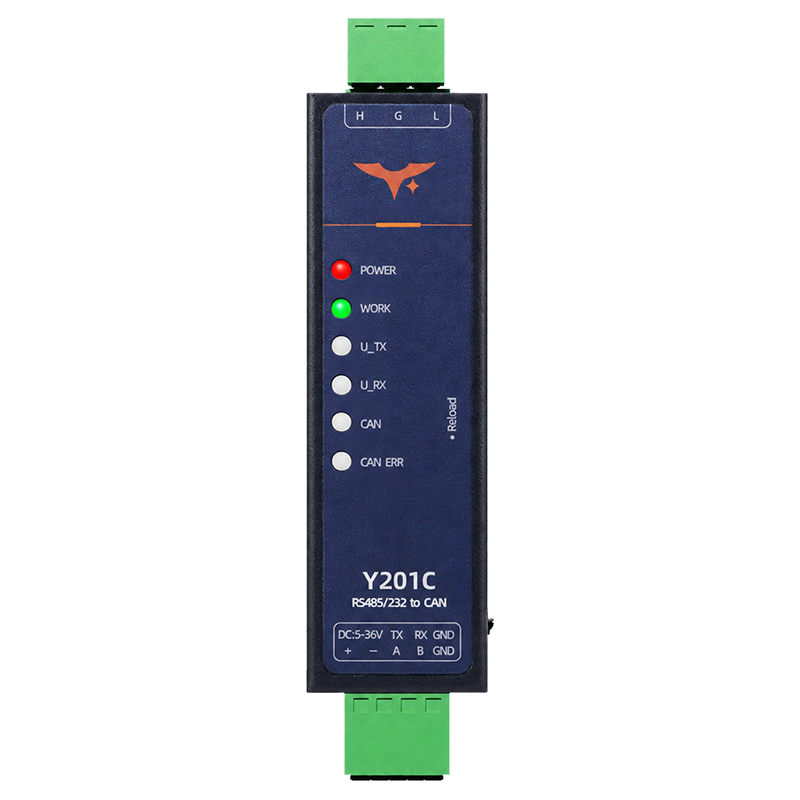
Y201C has one CAN channel and one ordered serial interface. Ethernet and additional CAN channels are not part of this model.
Contents
- Overview
- Default Settings
- Wiring and Commissioning
- Serial Modes and Packetization
- CAN Configuration and Data Formats
- Modbus RTU Conversion
- AT Command Conventions
- Common AT Commands
- Configuration Examples
- Maintenance and Troubleshooting
1. Overview
Y201C transfers data bidirectionally between one CAN 2.0 A/B channel and one ordered serial interface. The serial interface is available as RS232, RS485, or TTL, depending on the hardware variant. The TTL voltage level is not specified; verify it for the ordered variant before wiring. Configure the gateway through a configuration tool or serial AT commands.
| Item | Description |
|---|---|
| CAN Interface | One CAN channel, 10 to 1000 kbps |
| Serial Interface | RS232 / RS485 / TTL, depending on the ordered variant |
| Transfer Modes | DATA, ID_DATA, FRAME, MODBUS |
| Configuration | Configuration tool or serial AT commands |
| Maintenance | Backup parameters, factory reset, loopback, heartbeat, filters, serial upgrade |
2. Default Settings
| Parameter | Default |
|---|---|
| Serial Mode | Transparent mode |
| Serial Format | 115200 bps, 8 data bits, 1 stop bit, NONE parity |
| Serial Flow Control | NFC |
| Serial Packet Interval | 5 ms |
| Serial Packet Length | Firmware-dependent; query AT+UARTTL1=? or the configuration tool |
| CAN Baud Rate | 100 kbps |
| CAN Transfer Target | OFF in the AT-command table; set to UART for CAN-to-serial operation |
| CAN Transfer Mode | DATA |
| CAN Output Frame | Standard data frame; configure the CAN ID for the application |
| CAN Loopback | OFF |
| CAN Packet Split | ON |
| Serial Heartbeat | OFF; interval 60 s when enabled |
| CAN Heartbeat | OFF; interval 60000 ms when enabled |
| CAN Filters | OFF |
| Command Echo | OFF |
| Boot Information | Start |
Serial baud-rate and packet-length ranges depend on the firmware. Query the target firmware or configuration tool before using 1200 bps, 1024-byte packetization, or 1460-byte packetization.
3. Wiring and Commissioning
3.1 Hardware Connection
- Select the serial wiring for the ordered variant.
- Connect
5 to 36 VDCto+and-, observing polarity. - Connect the CAN bus to
H,G, andL.His CAN positive,Lis CAN negative, andGis CAN signal ground. - Connect the serial side:
- RS485:
AtoA,BtoB, and signal ground where required. - RS232 or TTL: peer
TXto deviceRX, peerRXto deviceTX, andGNDtoGND. Verify the TTL voltage level before wiring.
- RS485:
- Enable the built-in
120 Ωtermination only when the gateway is at a bus termination point. - Power on the device.
POWERshould remain on andWORKshould blink once per second.
Reload behavior is firmware-dependent. Check its function before using it for a factory reset. AT+RSTCFG restores backup parameters; AT+CLRCFG performs a full factory reset.
3.2 Configuration Tool
- Connect a PC to the ordered serial interface through the appropriate USB-to-RS485, USB-to-RS232, or TTL adapter.
- Open the configuration tool and select the CAN device type.
- Open the serial port with the default parameters
115200/N/8/1andNFCflow control. - Set the CAN baud rate, transfer target, transfer mode, frame parameters, packet split, heartbeat, and filters as required.
- Save the parameters and reboot the device.
- Send test data from both sides and verify the
UARTandCAN1indicators.
3.3 AT Configuration Entry
AT commands are available through the serial port. Use this sequence from transparent mode:
- Send
+++. - Wait longer than the packet interval and less than
3 s;500 msis recommended. - Send
a. - Wait for
+okbefore sending AT commands.
The device pauses CAN transparent output for up to about 3 s after receiving +++, but other data can still interfere with the sequence. AT mode is not retained after power loss or reboot.
To return to transparent mode, send AT+EXIT\r\n and wait for OK, or reboot the device.
4. Serial Modes and Packetization
4.1 Serial Working Modes
- Transparent mode, default: Serial data is packetized and forwarded through the CAN channel.
- AT command mode: Serial input is interpreted as AT commands. CAN transparent data is discarded while the device processes commands.
Each command line accepts one AT command. New settings are saved to the runtime parameter area and take effect after reboot.
4.2 Packetization
The gateway forwards serial data when either condition is met:
- Length trigger: received data reaches the configured packet length.
- Interval trigger: the gap between adjacent characters reaches the configured packet interval.
The active packet-length range and default depend on the firmware. Use the value reported by the target firmware's help response or configuration tool.
Example:
text
AT+UARTTL1=5,14604.3 Serial Heartbeat
The serial heartbeat sends a user-defined hexadecimal packet at a configured interval.
| Parameter | Range / Default |
|---|---|
| Enable | OFF / ON, default OFF |
| Interval | 1 to 86400 s, default 60 s |
| Data | Hexadecimal string, 2 to 64 bytes |
Use AT+HEARTEN1, AT+HEARTTM1, and AT+HEARTDAT1 to configure it.
5. CAN Configuration and Data Formats
5.1 CAN Baud Rate
The CAN channel supports 10 to 1000 kbps and defaults to 100 kbps. The supported rate list may differ by firmware; query the target firmware before using 800 kbps.
The AT command expresses the rate in kbps. For example, 100 kbps is written as 100 and 1 Mbps as 1000.
5.2 Transfer Target
Y201C has one CAN channel and one serial channel. Set the CAN transfer target to UART for bidirectional CAN-to-serial transfer:
text
AT+CAN1=100,UART,DATAUse UART as the transfer target on Y201C. CAN and ALL are transfer targets for multi-CAN variants.
5.3 Transfer Modes
| Mode | Serial-to-CAN Behavior | CAN-to-Serial Behavior |
|---|---|---|
DATA | Places the serial packet in the CAN data field and uses the configured CAN frame parameters | Returns the CAN data field only |
ID_DATA | Parses the serial packet as CAN ID followed by data; standard-frame ID uses 2 bytes and extended-frame ID uses 4 bytes | Returns CAN ID followed by data |
FRAME | Parses a complete frame containing frame information, a 4-byte ID, and 0 to 8 data bytes | Returns the same complete-frame structure |
MODBUS | Converts validated Modbus RTU data to segmented CAN data | Reassembles segmented CAN data and adds the Modbus RTU CRC before serial output |
Select a mode with the third parameter of AT+CAN1:
text
AT+CAN1=100,UART,DATA
AT+CAN1=100,UART,ID_DATA
AT+CAN1=100,UART,FRAME
AT+CAN1=100,UART,MODBUS
5.4 Output Frame Parameters
For DATA mode, configure the CAN frame format, frame type, and ID separately:
text
AT+CAN1FRAME=STD,DATA,128| Parameter | Values |
|---|---|
| Frame Format | STD standard frame / EXT extended frame |
| Frame Type | DATA data frame / REMOTE remote frame |
| Frame ID | Decimal CAN ID; use the range supported by the selected frame format |
These parameters define the CAN frame generated from serial data. They do not rewrite or filter frame information received directly from the CAN bus.
5.5 Complete-Frame Format
FRAME mode uses this serial structure:
text
[Frame Information: 1 byte][CAN ID: 4 bytes][Data: 0 to 8 bytes]The frame-information byte uses these bits:
| Bits | Field | Meaning |
|---|---|---|
| 7 | IDE | 0 standard frame; 1 extended frame |
| 6 | RTR | 0 data frame; 1 remote frame |
| 5 to 4 | Reserved | Reserved |
| 3 to 0 | DLC | CAN data length |
The CAN ID field occupies 4 bytes for both standard and extended frames. For example, a standard data frame with ID 0x123 and eight data bytes is represented as:
text
08 00 00 01 23 11 22 33 44 55 66 77 885.6 Packet Splitting
When packet splitting is enabled, serial data that exceeds the maximum CAN data length is divided into multiple CAN frames. When packet splitting is disabled, an overlength serial packet is treated as invalid and is not forwarded.
text
AT+CAN1SPLIT=ONFor DATA mode, each CAN frame carries up to eight data bytes. In FRAME mode, each complete frame is checked for a valid frame-information byte, CAN ID, and data length before forwarding.
5.7 CAN Loopback
Loopback causes CAN frames transmitted by the channel to be received by the same channel and processed according to the configured transfer direction and mode. Use it for bench testing only.
text
AT+CAN1LOOP=ONDisable loopback before connecting the gateway to a live CAN bus. CAN filters still apply to loopback data.
5.8 CAN Heartbeat
The CAN heartbeat periodically transmits a configured CAN frame.
text
AT+CAN1HTEN=ON
AT+CAN1HTTM=60000
AT+CAN1HTFRAME=STD,DATA,1792
AT+CAN1HTDATA=1122334455667788| Parameter | Range / Default |
|---|---|
| Enable | OFF / ON, default OFF |
| Interval | 10 to 86400000 ms, default 60000 ms |
| Frame Format | STD / EXT, default STD |
| Frame Type | DATA / REMOTE, default DATA |
| Frame ID | Decimal, default 1792 (0x700) |
| Data | Hexadecimal string, 2 to 16 bytes |
5.9 CAN Filters
Y201C provides eight independent filters for the CAN channel. A frame is accepted when it matches any enabled filter.
| Filter Parameter | Values |
|---|---|
| Status | ON / OFF, default OFF |
| Frame Format | STD / EXT / ALL |
| Filter Mode | ID exact ID / MASK ID-plus-mask |
| ID | Decimal, 0 to 536870911 |
| Mask | Decimal; default 536870911 (0x1FFFFFFF) |
For filter m, use AT+CAN1FLTm, replacing m with 1 to 8. With MASK mode, all ID bits whose mask bit is 1 must match the configured ID.
Example for filter 2:
text
AT+CAN1FLT2=ON,STD,MASK,291,256This accepts standard frames whose masked ID matches decimal 291 (0x123) with mask decimal 256 (0x100).
6. Modbus RTU Conversion
6.1 Function Description
In MODBUS mode, the serial side uses standard Modbus RTU. The gateway validates the serial frame and discards invalid data. It does not operate as a Modbus master or slave; it verifies and forwards protocol data.
The maximum Modbus RTU frame length is 219 bytes. When CAN data is reassembled for serial output, the gateway completes the Modbus RTU CRC before forwarding the frame.
Modbus conversion does not support CAN-to-CAN forwarding.
6.2 CAN Segmentation
CAN data uses one segmentation header byte followed by up to seven Modbus data bytes per CAN frame:
text
CAN data 1: [Segment Marker][Segment Type][Segment Counter]
CAN data 2 to 8: Modbus data bytes
The segmentation header uses:
| Bits | Field | Meaning |
|---|---|---|
| 7 | Segment marker | 0 standalone frame; 1 segmented frame |
| 6 to 5 | Segment type | 0 first; 1 middle; 2 last |
| 4 to 0 | Segment counter | Segment sequence number, 1 to 31 |
Configure Modbus conversion with:
text
AT+CAN1=100,UART,MODBUS7. AT Command Conventions
7.1 Format Rules
- Commands start with
AT+and end with\r\n. - Commands are case-insensitive; uppercase is recommended.
- One command is allowed per line.
- The maximum command length is
256 bytes. - Separate multiple parameters with an ASCII comma.
- Wait for the previous response before sending the next command; the maximum command timeout is about
5 s.
7.2 Call Types
| Type | Send Format | Return Format |
|---|---|---|
| Query | AT+CMD\r\n or AT+CMD?\r\n | +CMD:value followed by OK |
| Set | AT+CMD=value1,value2...\r\n | OK |
| Help | AT+CMD=?\r\n | +CMD:(range...) followed by OK |
Command examples omit the final \r\n unless noted otherwise.
7.3 Error Codes
| Error Code | Meaning |
|---|---|
ARGS | Invalid parameter length, value, format, or range |
ARGC | Invalid number of parameters |
CMD_UNKNOWN | Unknown command |
CMD_FORMAT | Invalid command format, such as missing AT+ |
CMD_LENGTH | Command exceeds the maximum length |
DEV_MEMORY | Device memory error |
DEV_SAVE | Parameter save error |
8. Common AT Commands
8.1 Device and Parameter Control
| Command | Function | Notes |
|---|---|---|
AT+LIST | List supported commands | Query the command set on the target firmware |
AT+VER | Query firmware version | Returns the version string |
AT+DEVINFO | Query device information | Model, version, MAC, build, production time, and serial number |
AT+ECHO | Query or set command echo | ON / OFF; default OFF |
AT+BOOTINFO | Query or set boot information | 1 to 16 bytes; default Start |
AT+REBOOT | Reboot the device | Applies saved runtime parameters after reboot |
AT+EXIT | Exit AT mode | Returns to transparent mode |
AT+RSTCFG | Restore backup parameters and reboot | Equivalent to Reload recovery |
AT+BKCFG | Back up current runtime parameters | Recommended after commissioning |
AT+CLRCFG | Restore factory parameters and reboot | Full factory reset |
8.2 Serial Parameters
| Command | Function | Range / Default |
|---|---|---|
AT+UART1=<baud>,<data>,<stop>,<parity>,<fc> | Serial settings | Baud list is firmware-dependent; default 115200,8,1,NONE,NFC |
AT+UARTTL1=<tm>,<len> | Packet interval and length | tm 1 to 300 ms, default 5; len follows the firmware's reported range |
AT+HEARTEN1=<state> | Serial heartbeat enable | ON / OFF; default OFF |
AT+HEARTTM1=<time> | Serial heartbeat interval | 1 to 86400 s, default 60 |
AT+HEARTDAT1=<data> | Serial heartbeat data | Hexadecimal string, 2 to 64 bytes |
8.3 CAN Parameters
| Command | Function | Range / Default |
|---|---|---|
AT+CAN1=<bps>,<target>,<mode> | CAN rate, transfer target, and mode | target=UART; mode DATA / ID_DATA / FRAME / MODBUS; rate default 100 |
AT+CAN1FRAME=<format>,<type>,<id> | Output frame parameters | STD/EXT, DATA/REMOTE, decimal ID |
AT+CAN1LOOP=<state> | CAN loopback | ON / OFF; default OFF |
AT+CAN1SPLIT=<state> | Serial data splitting | ON / OFF; default ON |
AT+CAN1HTEN=<state> | CAN heartbeat enable | ON / OFF; default OFF |
AT+CAN1HTTM=<time> | CAN heartbeat interval | 10 to 86400000 ms, default 60000 |
AT+CAN1HTFRAME=<format>,<type>,<id> | CAN heartbeat frame | Default STD,DATA,1792 |
AT+CAN1HTDATA=<data> | CAN heartbeat data | Hexadecimal string, 2 to 16 bytes |
AT+CAN1FLTm=<state>,<format>,<mode>,<id>,<mask> | Filter m | m=1 to 8; STD/EXT/ALL; ID/MASK |
9. Configuration Examples
9.1 CAN-to-Serial Data-Only Transfer
- Enter AT mode with
+++, a short delay, anda; wait for+ok. - Match the serial parameters to the host:
text
AT+UART1=115200,8,1,NONE,NFC
AT+UARTTL1=5,1460- Configure the CAN channel and output frame:
text
AT+CAN1=100,UART,DATA
AT+CAN1FRAME=STD,DATA,128
AT+CAN1SPLIT=ON- Save a recovery copy and reboot:
text
AT+BKCFG
AT+REBOOT- Send up to eight data bytes from the serial side and check that the CAN analyzer receives a standard data frame with ID
128.
9.2 Complete-Frame Transfer
Use complete-frame mode when the host must specify or receive the CAN frame format, frame type, ID, and data length:
text
AT+CAN1=100,UART,FRAME
AT+BKCFG
AT+REBOOT
Send and receive the complete-frame structure described in 5.5.
9.3 Modbus RTU over CAN
- Match the serial parameters to the Modbus RTU master or slave.
- Select Modbus conversion:
text
AT+CAN1=100,UART,MODBUS
AT+BKCFG
AT+REBOOT- Send a valid Modbus RTU frame from the serial side.
- Reassemble the segmented CAN frames at the remote CAN endpoint according to 6.2.
- Check that invalid CRC or malformed Modbus frames are discarded.
9.4 Filtering and Heartbeat
Enable only the filters and heartbeat packets required by the application:
text
AT+CAN1FLT1=ON,STD,MASK,291,536870911
AT+CAN1HTEN=ON
AT+CAN1HTTM=60000
AT+CAN1HTFRAME=STD,DATA,1792
AT+CAN1HTDATA=1122334455667788
AT+BKCFG
AT+REBOOT
Review the CAN analyzer after reboot to see whether unrelated IDs are filtered and the heartbeat is transmitted at the expected interval.
10. Maintenance and Troubleshooting
10.1 Parameter Areas
The gateway uses three parameter areas:
- Runtime area: The active configuration queried and changed by AT commands.
- Backup area: A recovery copy written by
AT+BKCFGand restored byAT+RSTCFGor Reload. - Factory area: Manufacturer-fixed defaults restored by
AT+CLRCFG.
Recommended workflow:
- Configure and test the runtime parameters.
- Run
AT+BKCFGafter commissioning. - Use
AT+RSTCFGwhen the backup configuration must be restored. - Use
AT+CLRCFGonly when a full factory reset is required.
10.2 Firmware Upgrade
- Power off the gateway.
- Hold the
Reloadbutton while powering it on. - Release the button after the device enters serial upgrade mode;
WORKfast-blinks. - Use the configuration tool to load the firmware.
- Recheck the serial, CAN, heartbeat, filter, and packetization settings after the upgrade.
10.3 Troubleshooting
| Symptom | Possible Cause | Recommended Action |
|---|---|---|
No POWER LED | Power wiring or polarity is wrong | Check +/-, supply voltage, terminal seating, and reverse polarity |
No +ok after AT entry | Timing is incorrect or another data source interferes | Retry +++, wait about 500 ms, send a, and wait for +ok |
| Serial data does not reach CAN | Transfer target is OFF, wrong CAN rate, or wrong mode | Set AT+CAN1=...,UART,...; match the CAN baud rate and frame mode |
| CAN data does not reach serial | Wrong wiring, filter, or CAN frame format | Check H/G/L, disable filters for testing, and verify DATA, ID_DATA, or FRAME format |
| CAN bus reports errors | Rate mismatch, wiring fault, or termination problem | Match the baud rate, check polarity and signal ground, and apply 120 Ω termination only at the bus end |
| Long serial packet is discarded | Packet splitting is disabled or packet length exceeds the active limit | Enable AT+CAN1SPLIT=ON and query AT+UARTTL1=? |
| Modbus frame is discarded | CRC, function frame, or segment data is invalid | Validate the Modbus RTU frame and reassemble CAN segments in order |
| Heartbeat is absent | Heartbeat is disabled or parameters were not applied | Enable the correct heartbeat, save with AT+BKCFG, and reboot |
| Filtered data is missing | An enabled filter does not match the CAN ID | Disable filters temporarily or check STD/EXT, ID, and mask values |
| Parameters return after Reload | Desired values were not backed up | Reconfigure the device and run AT+BKCFG |
10.4 LED Reference
POWERsteady on: power is present.WORKblinks once per second: normal operation.WORKfast-blinks: serial firmware upgrade mode.UART TX/UART RX: serial activity.CAN1: CAN data activity.CAN1 ERR: CAN error indication.
- Manufacturer: Hunan YenGear Tech Co., Ltd.
- Address: Room 21014, Building 1, Fudi Xingguang Tiandi, Yingxin Road, Yuhua District, Changsha, Hunan, China
- Email: [email protected]
- Website: www.yengear.com