
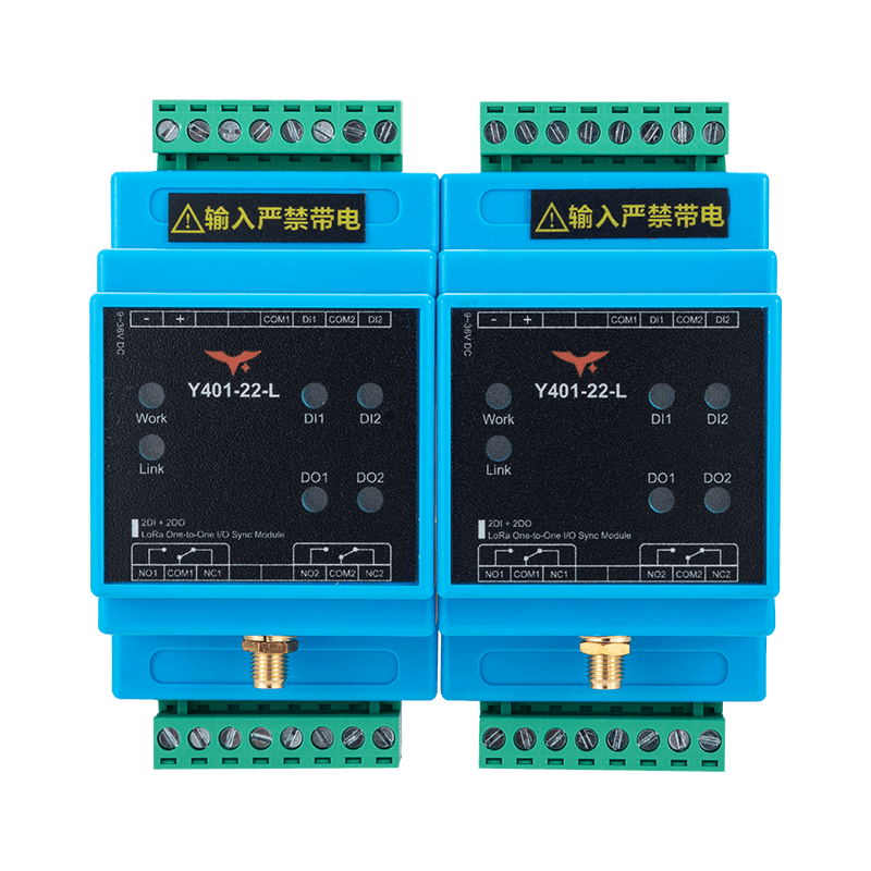
Appearance
Y401-22-L LoRa Wireless I/O Module Datasheet
Contents
- Overview
- Ordering Information
- Key Features
- Technical Specifications
- Interfaces and Indicators
- Mechanical and Environmental
- Installation and Wiring
- Important Notes
1. Overview
The Y401-22-L is a dual-channel point-to-point wireless I/O terminal based on LoRa modulation. Two units (Device A and Device B) are factory paired. The two channels operate independently and are ready to use without additional setup.

Operating Logic
- Device A
DIclosed -> the correspondingDOon Device B energizes - Device A
DIopen -> the correspondingDOon Device B resets - Bidirectional operation: the same logic applies from Device B to Device A
Channel Mapping
| Device A | Device B |
|---|---|
| Channel 1 input | Channel 1 output |
| Channel 2 input | Channel 2 output |
Typical Applications
Remote equipment control, multi-pump interlock, gate control, and alarm systems
2. Ordering Information
Model Configuration
Y401-22-L is a one-to-one LoRa pair. The two digits, 22, specify the digital I/O count on the two sides: each device has 2 DI and 2 DO.
For the full code and examples, see Model Naming.
Package Contents
| Qty. | Item |
|---|---|
| 2 | Y401-22-L modules (Device A and Device B) |
| 2 | 470 MHz magnetic-mount antennas |
| 2 | DIN rail clips |
| 1 | Quick reference guide |
| 1 | Warranty card |
3. Key Features
- Dual-channel control - Two independent channels with no cross-interference
- Long-range communication - Up to 5 km standard in open areas; a 10 km option is available for selected configurations
- Plug-and-play deployment - Factory paired, no configuration required
- Wide supply range - 9 to 36V DC with reverse-polarity protection
- Relay output - 2 x SPDT relays, rated at AC 277V 5A / DC 28V 5A
- Dry contact / NPN DI - Supports passive dry contacts and NPN open-collector inputs
- Status indication - LEDs for power, link, input, and output status
- Industrial design - Hardware watchdog and 35 mm DIN rail mounting
- No operating fee - No SIM card and no subscription required
4. Technical Specifications
Wireless
| Parameter | Specification |
|---|---|
| Frequency band | 398 to 525 MHz |
| Communication range | Up to 5 km standard; 10 km option available for selected configurations |
| Antenna connector | SMA |
| Standard antenna | 470 MHz magnetic-mount antenna |
Electrical
| Parameter | Specification |
|---|---|
| Supply voltage | 9 to 36V DC |
| Max. power consumption | 1.5W |
| Input channels | 2 x passive dry contact / NPN open-collector (no voltage input to DI) |
| Output channels | 2 x SPDT relay |
| Output rating | AC 277V 5A / DC 28V 5A |
| Operating temperature | -20 to +85 degC |
| Operating humidity | 10% to 90% RH, non-condensing |
5. Interfaces and Indicators
Interface Summary
| Interface | Description |
|---|---|
| Antenna | SMA connector for LoRa antenna |
| Power | DC 9 to 36V input with reverse-polarity protection |
| Input | 2 x passive switch input (DI + COM) |
| Output | 2 x relay output (NO + COM + NC) |
LED Indicators
| LED | Function | Status |
|---|---|---|
| Power | System status | On after power-up |
| Link | Link status | On when the wireless link is established |
| Input 1 / 2 | Input status | On when the corresponding DI is closed |
| Output 1 / 2 | Output status | On when the corresponding relay is energized |
6. Mechanical and Environmental
Mechanical Specifications
| Parameter | Specification |
|---|---|
| Dimensions | 88 x 72 x 59 mm |
| Weight | Approx. 50 g |
| Mounting | 35 mm DIN rail |
| Protection rating | IP20 |
| Housing material | Flame-retardant plastic |
7. Installation and Wiring
Input Wiring
No voltage input on DI
The digital input (DI) is not a voltage-input terminal. It is strictly forbidden to connect any powered signal or voltage source to DI.
Correct wiring: connect only a passive dry contact or an NPN open-collector output between DI and COM. Do not connect sensor power, PLC voltage output, or any external voltage directly to DI.
Mechanical switches (maintained switch, float switch, relay contact):
- Connect directly between
DIandCOM - No external power supply is required
NPN open-collector output:
- Output transistor collector ->
DI - Output transistor emitter / 0V reference ->
COM - Do not connect sensor power or any voltage output to
DI
Output Wiring
Direct load (<= 1 kW resistive load):
- Wire the load in series with the relay output
High-power load (> 1 kW):
- Use an AC contactor or external power relay
Installation Notes
- Install the antenna vertically in an open area, about 2 m above ground.
- Keep the unit away from large metal structures.
- Tighten the antenna connector securely.
- Mount the unit inside the control cabinet on a 35 mm DIN rail.
- Leave enough space for ventilation.
8. Important Notes
- Communication mode - Half-duplex communication, not intended for hard real-time control.
- Frequency range - Recommended operating range is 398 to 525 MHz. Performance may degrade outside this range.
- Antenna placement - Install the antenna vertically in an open area and keep it away from metal obstructions.
- Channel isolation - The two channels operate independently without mutual interference.
- Manufacturer: Hunan YenGear Tech Co., Ltd.
- Address: Room 21014, Building 1, Fudi Xingguang Tiandi, Yingxin Road, Yuhua District, Changsha, Hunan, China
- Email: [email protected]
- Website: www.yengear.com