
Appearance
Y401-1111-L LoRa Wireless Analog and Digital I/O Module Specification
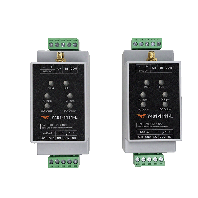
1. Overview
Y401-1111-L is a point-to-point LoRa wireless I/O pair. Each module provides 1 AI, 1 AO, 1 DI and 1 DO. The analog channels carry 4–20 mA signals; the digital output is an SPDT relay. Each device transfers its input signals to the corresponding outputs on the other device. Analog and digital channels operate independently.
| Direction | Analog signal | Digital signal |
|---|---|---|
| A to B | A AI → B AO | A DI → B relay |
| B to A | B AI → A AO | B DI → A relay |
The pair is supplied preconfigured for normal operation. The wireless link is half-duplex; transmission delay varies with site conditions.
2. Ordering Information
A standard system consists of two Y401-1111-L devices. Each has the same I/O complement. See the selection guide for other configurations.
3. Key Features
- Bidirectional analog and digital signal transfer over one point-to-point link
- 4–20 mA active current input and active current output
- Dry-contact or NPN input and changeover relay output
- Reverse-polarity protection and 35 mm DIN rail mounting
4. Technical Specifications
Wireless
| Parameter | Specification |
|---|---|
| Communication | LoRa, point-to-point, half-duplex |
| Range | Up to 5 km in open areas; actual range depends on antenna installation, obstructions and interference |
| Antenna | SMA connector; 470 MHz magnetic-mount antenna option |
| Antenna operating band | 410.125 to 493.125 MHz |
Electrical
| Parameter | Specification |
|---|---|
| Supply | 9 to 36 V DC |
| Maximum power consumption | Approx. 2 W |
| Analog input | 1 × 4–20 mA, active current source; source voltage at least 10 V; maximum input current 24 mA |
| Input acquisition accuracy | ≤ ±0.3 mA |
| Analog output | 1 × 4–20 mA, active constant-current output; load ≤ 500 ohms |
| Output error | ≤ ±0.3 mA |
| Digital input | 1 passive dry-contact or NPN input |
| Digital output | 1 SPDT relay, 277 V AC / 5 A or 28 V DC / 5 A |
| Terminals | 5.08 mm pitch pluggable terminals |
Input accuracy and output error are separate limits, not a guaranteed end-to-end accuracy. At 20 mA, a 500 ohm load alone requires 10 V; verify output headroom at the selected supply voltage and total load.
5. Interfaces and Indicators
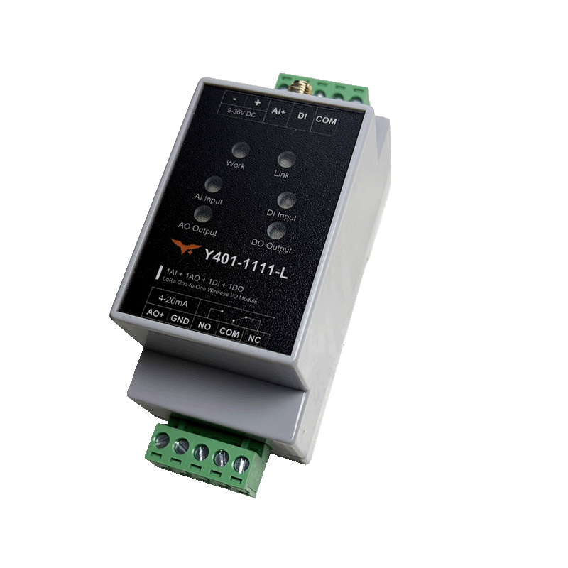
Viewed from the front, the terminal positions run left to right. Follow the markings on the device.
| Position | Upper row | Lower row |
|---|---|---|
| 1 | Power − | AO+ current output |
| 2 | Power + | GND, analog output return |
| 3 | AI+ current input | NO, relay normally open |
| 4 | DI, digital input | COM, relay common |
| 5 | COM, shared input return | NC, relay normally closed |
The upper COM is the return for AI and DI; the lower COM belongs to the relay. Do not assume galvanic isolation between power and signal circuits.
| Indicator | Meaning |
|---|---|
| Work | On after startup |
| Link | On when connected, off when disconnected; flashing indicates abnormal communication |
| AI Input | On when input current is detected |
| AO Output | On when output current is produced |
| DI Input | On when DI and upper COM are closed |
| DO Output | On when relay NO and lower COM are connected; off when NC and COM are connected |
6. Mechanical and Environmental
| Parameter | Specification |
|---|---|
| Dimensions | Manufacturer's enclosure table: 87.5 × 42.5 × 59 mm; dimension drawing: 43 × 111 × 59 mm (width × overall height × depth) |
| Weight | Approx. 100 g |
| Mounting | 35 mm DIN rail |
| Operating temperature | −20 to +75 °C |
| Operating humidity | 10% to 90% RH, non-condensing |
The table and drawing use different height and width values. Confirm dimensions against the actual device before designing a tight enclosure.
7. Installation and Wiring
Use the user manual for analog and digital wiring, pairing and configuration, and commissioning.
AI accepts an active current source; AO connects to a compatible passive current receiver. The upper COM is the shared input return; the lower COM is the relay contact common. DI accepts a voltage-free contact or NPN output. Relay contacts require a separate load supply. Observe the electrical limits above.
8. Important Notes
- The half-duplex wireless link has variable delay and is unsuitable for guaranteed timing or as the sole emergency-stop/personnel-safety path.
- Input acquisition accuracy and output error are separate limits, not a stated end-to-end accuracy. Output loading also depends on supply headroom.
- The manufacturer does not specify the analog or relay output state or timeout during link loss. Test link loss and recovery with control loads isolated and provide independent protection for the process.
- Contact YenGear for replacement or re-pairing instructions.
- Manufacturer: Hunan YenGear Tech Co., Ltd.
- Email: [email protected]
- Website: www.yengear.com