
Appearance
Y401-1111-L Wireless Analog and Digital I/O Module User Manual
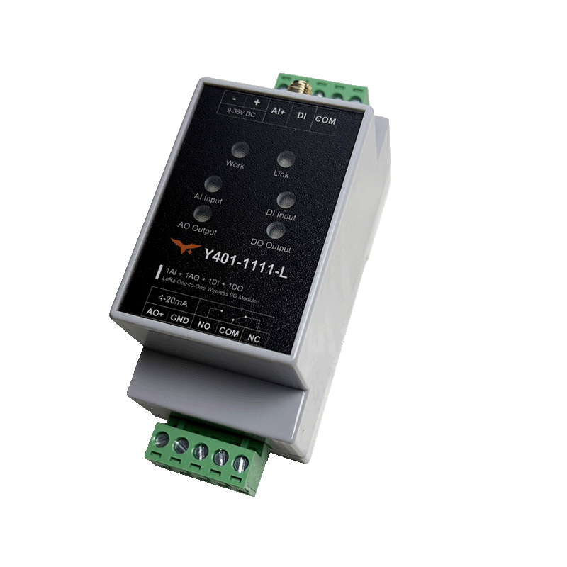
Product Introduction
The Y401-1111-L transfers analog and digital signals between two paired modules over a point-to-point LoRa link. Each module has one 4–20 mA analog input (AI), one 4–20 mA analog output (AO), one digital input (DI), and one relay output (DO).
Use the specification for dimensions, electrical ratings, accuracy, wireless parameters, and environmental limits. Use the selection guide to compare models.
Operating Logic
Channel Mapping
The two modules, Device A and Device B, exchange analog and digital signals in both directions. Analog and digital channels operate independently.
| Direction | Analog | Digital |
|---|---|---|
| A to B | A AI → B AO | A DI → B relay |
| B to A | B AI → A AO | B DI → A relay |
With the link operating, closing a DI to input COM energizes the remote relay: its NO–COM contact closes and NC–COM opens. Opening the input returns the remote relay to its de-energized state. The analog output reproduces the current received from the other module's analog input.
The wireless link is half-duplex. Delay varies with distance and site conditions; it is not a guaranteed real-time link.
Communication Loss
The manufacturer does not specify the analog or relay output state or a timeout after link loss. Before connecting a control load, test link loss and recovery with the load isolated. Do not assume that either output holds its last value or resets after a particular interval. Provide independent protection for the controlled process.
Installation and Wiring
Disconnect module, instrument and load power before wiring. Follow the actual terminal markings. The upper-row COM is the shared return for AI and DI; the lower-row COM is the relay contact common. These terminals serve different circuits. Do not assume galvanic isolation between power and signal circuits.
| Position, left to right | Upper row | Lower row |
|---|---|---|
| 1 | Power − | AO+ |
| 2 | Power + | GND, AO return |
| 3 | AI+ | NO, relay normally open |
| 4 | DI | COM, relay common |
| 5 | COM, AI and DI return | NC, relay normally closed |
Power and Antenna
- Connect each module's marked power + and − terminals to a 9–36 V DC supply. Check polarity. The field transmitter and receiving instrument require power according to their own ratings.
- Connect the matching antenna to each SMA connector before power-up. Mount each antenna vertically in an open location, about 2 m above ground where practical, away from large metal structures and outside metal cabinets.
- Mount each module on a stable 35 mm DIN rail in a suitable enclosure. Check reception at the installed locations.
4–20 mA Input Wiring
AI accepts an active 4–20 mA current source. The source voltage must be at least 10 V and input current must not exceed 24 mA. Select the field instrument's supply according to its rating and the input source requirement.
Two-wire current transmitter
- Connect loop supply positive to transmitter positive.
- Connect transmitter current return to module AI+.
- Connect upper COM to loop supply negative.
The transmitter loop and module may use separate supplies. A shared supply is also possible if it meets both the transmitter requirements and the module's 9–36 V DC rating. AI+ is a signal input, not a transmitter power output.
Three-wire current transmitter
- Connect transmitter power positive to its rated supply positive.
- Connect transmitter signal output to AI+.
- Connect transmitter common power/signal return and supply negative to upper COM.
Four-wire current transmitter or signal generator
- Connect the instrument power pair to its rated supply.
- Connect the separate signal positive to AI+ and signal negative to upper COM.
Current input
Do not connect a voltage signal or an external voltage source directly across AI+ and COM. A loop supply powers a two-wire transmitter through the current loop; it must not be wired directly across the module input.
4–20 mA Output Wiring
Connect lower-row AO+ to a compatible passive receiver's signal positive and adjacent GND to its signal negative. AO is an active constant-current output; do not connect it directly to another active current source. The module's power connection is separate from this signal pair. Use a suitable isolator or converter if the receiver interface is incompatible.
Keep the total load, including receiver and wiring resistance, at or below 500 ohms. Verify supply headroom: a 500 ohm load alone requires 10 V at 20 mA, so operation at that load is not established by the 9 V minimum module supply.
Digital Input Wiring
Connect a voltage-free contact between DI and upper COM. For an NPN open-collector output, connect its collector to DI and emitter to upper COM; power the sensor according to its rating.
Do not apply voltage directly to DI. Convert a powered signal, including a PNP output, to a voltage-free contact with an interposing relay.
Relay Output Wiring
The relay contacts do not supply load voltage. For normally open operation, connect the external load supply and load in series through lower-row COM and NO. Use COM and NC when a normally closed contact is required. Select protection for the load and stay within the relay ratings of 5 A at 277 V AC or 28 V DC.
Use a suitably rated external contactor or power relay and appropriate surge suppression for larger or inductive loads. The module switches the contactor coil; the contactor switches the load. High-voltage wiring must be performed by qualified personnel.
Pairing and Configuration
Use the supplied matched pair. Normal operation requires no on-site configuration. Contact YenGear for replacement or re-pairing instructions. Do not apply another model's pairing procedure to this module's signal terminals.
Commissioning
Initial Setup and Indicators
Before power-up, check the matched pair, antennas, power polarity, instrument supplies, input returns, relay wiring and load ratings. Keep control loads isolated during functional checks.
| LED | Status |
|---|---|
| Work | On after startup |
| Link | On when connected; off when disconnected; flashing indicates abnormal communication |
| AI Input | On when input current is detected |
| AO Output | On while output current is produced |
| DI Input | On when DI and upper COM are closed |
| DO Output | On when relay NO–COM is connected; off when NC–COM is connected |
LEDs indicate activity, not measurement accuracy.
Functional Checks
- Connect the antennas and power both modules. Check Work and Link indicators.
- Apply known currents such as 4, 12 and 20 mA to Device A AI. Measure Device B AO with a compatible passive receiver or a meter in DC mA mode connected in series. Compare results using the separate input acquisition and output error limits in the specification; include instrument errors. Repeat from B to A.
- Close A DI to upper COM and check B relay NO–COM closes. Open A DI and check the relay returns to NC–COM. Repeat from B to A. Check that operating the digital channel does not disturb the analog path.
- Test at the installed locations. With control loads isolated, check output behavior during link loss and recovery before connecting loads.
Troubleshooting
| Symptom | Checks |
|---|---|
| No wireless link | Check power at both devices, matched pair, antenna connections, antenna placement and obstructions. |
| No analog output or wrong reading | Check source and receiver ranges, instrument power, AI polarity, upper COM return, AO polarity and receiver compatibility. Check loop load, supply headroom and meter mode. |
| DI indicator does not turn on | Check the dry contact or NPN connection between DI and upper COM. Do not apply voltage to DI. |
| Relay operates but the load does not | Check lower NO/COM/NC selection, external load supply, protection and wiring. The relay does not supply voltage. |
| Outputs change after a link interruption | Isolate the loads, check the link and evaluate actual output behavior before restoring control. |
Safety Notes
- Disconnect power before wiring; confirm polarity and ratings before power-up.
- Do not exceed the current input, analog output load, or relay limits. Protect inductive loads with suitable switching and suppression.
- Protect the device from liquids, heat, heavy dust and strong interference. Do not install it in an explosive environment or disassemble it.
- Do not use the wireless link as the sole emergency-stop or personnel-safety path. Validate the complete system before connecting control loads.
- Manufacturer: Hunan YenGear Tech Co., Ltd.
- Address: Room 21014, Building 1, Fudi Xingguang Tiandi, Yingxin Road, Yuhua District, Changsha, Hunan, China
- Email: [email protected]
- Website: www.yengear.com