
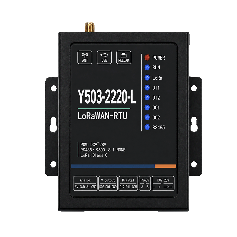
Appearance
Y503-2220-L LoRaWAN RTU Specification
User Manual: Y503-2220-L User Manual
Contents
- Overview
- Model and Signal Configuration
- Key Features
- Technical Specifications
- Interfaces and Indicators
- Mechanical and Package Information
- Deployment and Ordering
1. Overview
Y503-2220-L connects digital signals, analog sensors, and RS485 equipment to a LoRaWAN network. It provides two digital inputs, two switched voltage outputs, and two analog inputs: one 0–10 V input and one 4–20 mA input.
The RTU sends measurements through a LoRaWAN gateway and Network Server to an application. Downlink commands control the outputs and supported serial functions.
| Item | Specification |
|---|---|
| Product type | Industrial LoRaWAN remote terminal unit (RTU) |
| Signal configuration | 2 DI + 2 DO + 2 analog inputs; no analog output |
| Analog input allocation | 1 × AV: 0–10 V; 1 × AI: 4–20 mA |
| Serial interface | 1 isolated RS485 |
| LoRaWAN version | 1.0.3 |
| Activation / device class | OTAA or ABP / Class A or Class C |
| Regional plans | EU433, CN470, EU868, AU915, US915, AS923 |
| Reference deployment plan | CN470; select the hardware variant before ordering |
2. Model and Signal Configuration
The four digits in Y503-2220-L represent DI / DO / AI / AO channel counts: 2 / 2 / 2 / 0. The third digit counts the dedicated AV and AI inputs together; the final 0 indicates no analog output.
| Signal | Quantity | Function |
|---|---|---|
| DI1, DI2 | 2 | Dry-contact or powered digital input, up to DC 28 V |
| DO1, DO2 | 2 | Switched voltage outputs; on-state voltage follows the RTU supply |
| AV | 1 | 0–10 V measurement |
| AI | 1 | 4–20 mA measurement |
| AO | 0 | No analog output |
AV measures voltage and AI measures current; neither terminal switches between signal types. DO1 and DO2 switch the supply voltage to a load. Equipment that needs a voltage-free contact requires an external relay or suitable interface.
3. Key Features
- Periodic acquisition, heartbeat reporting, and input/output state-change reporting.
- RS485 polling and transparent serial transport, including Modbus RTU frames.
- Remote output commands, timed control, and pulse output on compatible firmware.
- Local input-to-output rules and remote parameter configuration on compatible firmware.
Use the installed firmware's configuration tool and command definitions to set timed, pulse, and local-rule behavior.
4. Technical Specifications
4.1 LoRaWAN Radio
| Parameter | Specification |
|---|---|
| Protocol | LoRaWAN 1.0.3 |
| Activation | OTAA / ABP |
| Device classes | Class A / Class C |
| Frequency plans | EU433, CN470, EU868, AU915, US915, AS923 |
| Transmit power | -1 to 22 dBm, subject to the regional configuration |
| Bandwidth | 125 kHz |
| Spreading factor | SF7–SF12 |
| Nominal radio data rates | Approximately 5.5 / 3.1 / 1.8 / 1.0 / 0.6 / 0.3 kbps |
| Receiver sensitivity | -135 dBm at SF12, 125 kHz bandwidth |
Specify the AS923 sub-plan when ordering. Airtime, payload size, reporting interval, retries, and regional limits reduce usable throughput below the nominal radio data rate.
4.2 Digital Inputs and Outputs
| Parameter | Specification |
|---|---|
| DI count | 2, with a shared COM terminal |
| DI signal types | Dry contact and powered contact; NPN/PNP wiring depends on the COM connection |
| Maximum DI voltage | DC 28 V |
| DO count | 2 switched voltage outputs |
| DO on-state voltage | Follows the applied RTU supply voltage |
| DO current limit | 1 A stated maximum; confirm the per-channel and combined limit for the intended load |
| Adapter requirement | Use a 2 A adapter when the connected output load exceeds 200 mA |
Check the per-channel and combined output limits before sizing the load; the stated rating does not specify two simultaneous 1 A outputs. Size the supply for the RTU, combined load, and starting current. Use a relay or driver for loads above the confirmed rating, with transient suppression for inductive loads.
4.3 Analog Inputs
| Parameter | AV terminal | AI terminal |
|---|---|---|
| Channel count | 1 | 1 |
| Input range | 0–10 V | 4–20 mA |
| Stated maximum input | 10.7 V | 22 mA |
| Accuracy | ±0.5% of full scale | ±0.5% of full scale |
| Resolution | 0.001 V | 0.001 mA |
Operate AV within 0–10 V and AI within 4–20 mA. The stated maxima are input limits, rather than measurement targets. Resolution is the reported step size.
4.4 RS485
| Parameter | Specification |
|---|---|
| Interface | 1 isolated RS485, A/B |
| ESD protection | 15 kV |
| Baud rates | 1200, 2400, 4800, 9600, 19200, 38400, 57600, 115200 bps |
| Data / stop bits | 8 / 1 or 2 |
| Parity | None, odd, or even |
| Initial serial setting | 9600 bps, 8 data bits, no parity, 1 stop bit |
| Operation | Scheduled polling and transparent transport, as configured |
Match serial settings, protocol, address, and command format with the equipment. Decode its responses using the firmware's payload definition and the equipment's register map.
4.5 Power and Environment
| Parameter | Specification |
|---|---|
| Supply | DC 9–28 V |
| Reference adapter | DC 12 V / 1 A; use a larger supply where required by the output load |
| Stated maximum working current | 0.5 A for the RTU; budget controlled loads separately |
| Stated average power | ≤0.5 W; load and operating conditions affect total consumption |
| Operating temperature | -40 to 85 °C |
| Storage temperature | -50 to 95 °C |
| Humidity | 5–95% RH, non-condensing |
5. Interfaces and Indicators
| Label | Connection or function |
|---|---|
| ANT | SMA female LoRa antenna connector |
| USB | Debug/log interface; follow the delivered service procedure |
| RELOAD | Short press: restart; hold for 5 s: restore factory settings |
| PE | Enclosure earth connection |
| AV, GND | Voltage input and reference |
| AI, GND | Current input and reference |
| DO2, DO1, GND | Switched voltage outputs and return |
| DI2, DI1, COM | Digital inputs and their common terminal |
| A, B | RS485 |
| −, + and DC jack | Parallel DC power inputs; use one supply |
| Indicator | Meaning |
|---|---|
| POWER | Steady: normal power; off: no power or a power fault |
| RUN | Blinking: normal operation; steady or off: check startup/fault status |
| LoRa | Radio transmission activity |
| DI1 / DI2 | Detected input state |
| DO1 / DO2 | Output voltage state |
| RS485 | Serial receive activity |
Check data reception in the application and output operation at the load; LEDs show local device activity.
6. Mechanical and Package Information
| Parameter | Specification |
|---|---|
| Enclosure dimensions | 104 × 97.6 × 25.6 mm |
| Stated weight | Approximately 0.7 kg |
| Installation | Wall or panel surface; follow the supplied mounting drawing |
| Reference package | RTU, DC 12 V / 1 A adapter, LoRa antenna, and mounting screws |
Check the order packing list for the supplied adapter, antenna, and mounting accessories.
7. Deployment and Ordering
Field signals / RS485 equipment → Y503-2220-L → LoRaWAN gateway → Network Server → Application
A Y501-L or Y511-L gateway provides the radio path with a matching frequency plan and channel group. The Network Server manages activation, sessions, and downlink scheduling. It runs remotely or on a gateway with optional local Network Server (NS) and Application Server (AS) software. The application decodes measurements and creates commands.
Specify the deployment settings when ordering:
- Regional plan, channel group, and AS923 sub-plan where applicable.
- Class A or Class C operation and the required reporting interval.
- DI sensor type and COM wiring; DO load voltage, current, and starting current.
- One voltage-input sensor and/or one current-input sensor.
- RS485 protocol, baud rate, device addresses, and polling commands.
- Firmware, configuration tool, uplink decoder, downlink command definition, and output behavior after startup or communication loss.
Downlink timing depends on device class, server scheduling, and radio capacity. Test command response time and load operation at the installation before enabling unattended control.
YenGear
Hunan YenGear Tech Co., Ltd.
Room 21014, Building 1, Fudi Xingguang Tiandi, Yingxin Road, Yuhua District, Changsha, Hunan, China
[email protected] · www.yengear.com