
Appearance
Y422-44-F Wireless Digital I/O Module User Manual
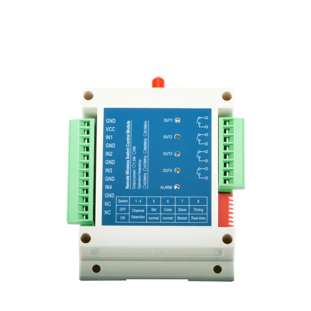
Product Introduction
Y422-44-F transfers four switch input states to the corresponding relay outputs on a compatible remote module. Each module has four inputs and four relay outputs. See the specification for electrical and wireless ratings.
Interfaces and Indicators

The diagram shows the front view and terminal numbers. Pins 11 and 12 are reserved; NC here does not mean a normally closed relay contact. Confirm the markings on the supplied module before wiring.
Operating Modes
A switch input shorted to GND energizes the corresponding remote relay; opening the input releases it. Wireless transmission introduces delay, so the link is not a deterministic safety circuit.
See DIP Switch Settings for the switch functions and settings for each mode.
Real-Time Mode
Set one module as master and the other as slave. In an unpaired one-to-one system, an input change on either module is sent to the corresponding output on the other. The module supports one master with five slaves. Channel pairing can distribute selected channels between multiple modules; confirm the mapping for a five-slave system before commissioning. See Channel Pairing.
Each module acknowledges received updates. If synchronization fails, the alarm turns on and the affected outputs open. The inquiry interval and actual timeout depend on the configuration; verify the output and recovery with the loads isolated.
Timing Mode
The master periodically sends its four input states to the slave, which updates its corresponding outputs. The slave inputs do not control the master outputs in this mode. The reference interval is 1 second and can be configured with the compatible PC interface; check the setting on the supplied module.
If the slave receives no update for five consecutive configured intervals, its alarm turns on and all four relay outputs open. Verify the timeout and recovery with loads isolated. Channel pairing is unavailable in timing mode.
Installation and Wiring
Disconnect power from both modules and loads before wiring. Confirm the labels on the supplied hardware.
| Pins | Terminal | Function |
|---|---|---|
| 1 / 2 | GND / VCC | DC supply negative / positive, 9–30 V DC |
| 3–10 | IN1 / GND through IN4 / GND | Four switch inputs; short each input to its GND to activate |
| 11 / 12 | NC | Reserved; leave unconnected |
| 13–20 | OUT1 through OUT4 | Two terminals per relay output |
Connect a dry contact between each IN and its adjacent GND. Use the two terminals of each output in series with an external supply and load. Confirm the relay voltage and current ratings, load type, and required protection with YenGear before wiring. Do not assume the output supplies power or provides a changeover contact.
Connect a 50 Ω antenna matched to the supplied frequency before powering the module. Install the antenna clear of metal structures and obstructions. Use a regulated supply with adequate current capacity; the reference supply is 12 V DC rated at 1 A or more per module. Check polarity before power-up.
DIP Switch Settings
The nominal ordering options are 433, 470, 868 and 915 MHz. Choose a matching version and antenna for each unit; do not assume a unit can switch between all four bands. Use the ordered frequency band. Confirm the exact operating frequency and permitted radio settings for the installation location; see the specification for frequency options.
Switch Functions
| Switch | ON | OFF |
|---|---|---|
| 1–4 | Frequency channel selection | Frequency channel selection |
| 5 | Normal operation | Configuration mode |
| 6 | Normal operation | Pairing mode |
| 7 | Master | Slave |
| 8 | Real-time | Timing |
Select a Frequency Channel
DIP 1–4 select one of 16 channels. The default spacing is 0.5 MHz, but the frequencies can be configured. Obtain the switch-to-channel table for the supplied hardware from YenGear and confirm the switch numbering and ON direction. Check the frequency table for each unit and select the same actual frequency: matching switch positions alone is insufficient if their frequency tables differ.
Set the Operating Mode
The diagrams show the switch viewed with positions 1–8 from left to right. A white slider toward ON indicates ON. DIP 1–4 are shaded because their settings depend on the channel plan; the shading does not indicate a switch position. Check the ON marking on the supplied module.
For real-time operation, use these settings on the master and slave:

For timing operation, use these settings on the master and slave:

For channel pairing, use the settings below. DIP 6 is OFF only while pairing; return it to ON for normal operation. See Channel Pairing for the steps.

Power-cycle after changing DIP settings. Changing DIP 7 or DIP 8 from the previous power-on setting clears existing channel pairings; record the mapping and re-pair if needed.
Channel Pairing and Mapping
Multi-Module Channel Mapping
In real-time mode, channel pairing can distribute the master's four channels among multiple slaves. The example below pairs each master channel with the matching numbered channel on a different slave. The dashed arrows show wireless signal paths, not wiring between modules.

For example, closing master IN1 energizes slave 1 OUT1; closing slave 1 IN1 energizes master OUT1. The other three channel pairs work likewise. This four-slave example does not define the channel mapping for a five-slave system or establish that one input can control all slave outputs simultaneously. Confirm the five-slave mapping before pairing. Multiple masters can also be paired to selected channels on one slave. Confirm the required mapping and test each direction with the loads isolated.
Channel Pairing
Pairing binds one master channel to one slave channel at a time. It is available in real-time mode only. An unpaired one-to-one system can operate without channel pairing; a multi-module mapping requires the selected channel pairs to be bound.
Before pairing, isolate the loads and disconnect module power. Give each module a unique address ID using the compatible PC interface, unless the IDs were already configured. Set DIP 1–4 to channels with the same actual frequency on both modules. Obtain the configuration interface and channel table from YenGear if needed.
Set the pairing switches on each unit as shown in DIP Switch Settings. Keep DIP 6 OFF during pairing, then return it to ON for normal operation.
Pair One Channel
- With both modules powered off, short the chosen slave input
INxto its adjacentGND. Leave the other inputs open. - Power the slave first. Its alarm indicator stays on when a channel is detected; a flashing indicator means no shorted input was detected.
- Short the chosen master input
INxto its adjacentGND, leaving the other inputs open. Power the master. Both alarm indicators go out when the channel pair succeeds. If they remain on, pairing has not succeeded. - Power off both modules and remove the temporary shorts. To bind more channels, repeat the procedure for one selected master/slave channel pair at a time. If more than one input is shorted on a unit, the reference gives priority to the lowest channel number.
- When all required pairs are complete, power off, set DIP 6 to ON on the units, and power them on for normal operation. Verify every intended input-to-output mapping in both directions with the loads isolated.
After a master channel has been paired, unpaired master channels do not transmit input changes. Switching the master/slave role or real-time/timing mode changes DIP 7 or 8 and clears existing pairings after power-up. Record the intended mapping and re-pair if needed; verify retained pairings and recovery on the supplied firmware.
Commissioning
- Isolate the loads and check power polarity, antennas, channel, roles and mode.
- In real-time mode, short and open each master input and check the matching slave output. Repeat from slave to master.
- In timing mode, test each master input against the matching slave output.
- With loads still isolated, interrupt the wireless link and check the actual output states and recovery before connecting equipment.
At power-up all relays open. Check the selected mode’s communication-loss behavior during commissioning.
Troubleshooting
| Symptom | Checks |
|---|---|
| No response or alarm on | Check supply, antennas, channel, roles, mode and pairing. |
| Wrong output | Check input and output channel numbers and wiring. |
| Relay operates but load does not | Check the external load supply, wiring and contact rating. |
| Intermittent operation | Check power stability, antenna placement, obstructions and interference. |
Safety Notes
- Keep control loads isolated during pairing and tests.
- Use suitably rated external protection and a contactor for loads beyond the verified relay rating.
- Do not use the wireless link as the only emergency-stop or personnel-safety path.
- Manufacturer: Hunan YenGear Tech Co., Ltd.
- Email: [email protected]
- Website: www.yengear.com