
Appearance
Y421-4444-L Wireless Analog and Digital I/O Module User Manual
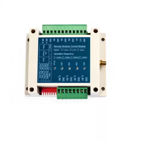
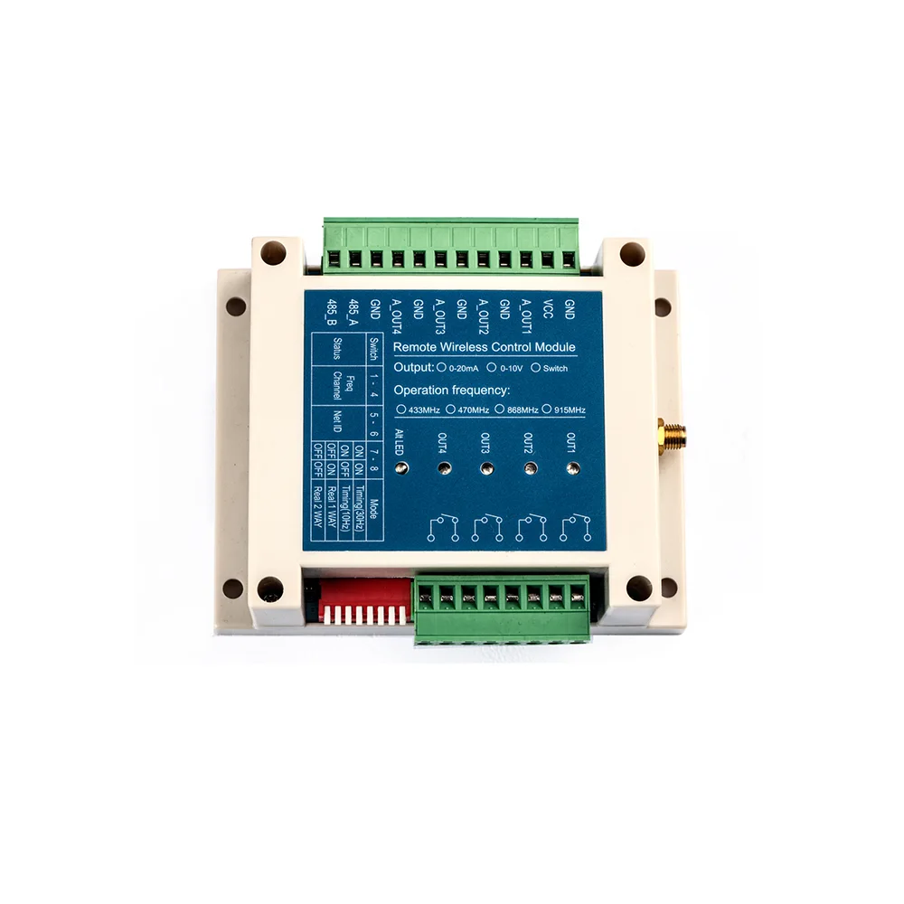
Product Introduction
Y421-4444-L transfers four current signals and four switch states from a transmitter (TX) to a receiver (RX). The receiver reproduces each signal on the corresponding output channel. See the specification for ratings and frequency options.
Interfaces and Indicators
The transmitter (TX) and receiver (RX) have different terminal functions. The diagrams show their front views and terminal numbers; confirm the markings on the supplied units before wiring.
Transmitter (TX)

Receiver (RX)

Operating Logic
| Transmitter | Receiver |
|---|---|
| IN1–IN4 | Corresponding relay output OUT1–OUT4 |
| A_IN1–A_IN4 | Corresponding current output A_OUT1–A_OUT4 |
The signal path is TX to RX. Some operating modes use radio responses from RX for communication monitoring; these do not provide reverse analog or digital I/O. Short a TX switch input to its adjacent GND to energize the matching RX relay; opening the input releases it. Updates and communication-loss actions depend on mode.
Installation and Wiring
Disconnect module and load power before wiring. Identify TX and RX from their labels and confirm the terminal markings on the supplied units.
| Pins | Transmitter (TX) | Receiver (RX) |
|---|---|---|
| 1 / 2 | GND / VCC: supply negative / positive | GND / VCC: supply negative / positive |
| 3–10 | IN1 / GND through IN4 / GND | A_OUT1 / GND through A_OUT4 / GND |
| 11 / 12 | 485_A / 485_B | 485_A / 485_B |
| 13–20 | GND / A_IN1 through GND / A_IN4 | Two terminals each for OUT1 through OUT4 |
Use a regulated 10–30 V DC supply for each unit and verify polarity. The reference supply is 12 V DC rated at 2 A or more per unit. Connect a 50 Ω antenna matched to the supplied frequency before power-up. Position the antennas clear of metal and obstructions.
Digital Input
Connect each dry contact between the TX IN and its adjacent GND.
Analog Input
Connect a current source to the TX A_IN and its associated GND. For a two-wire loop-powered sensor, use an external loop supply: connect supply positive to sensor positive, sensor negative to A_IN, and supply negative to the associated GND. Confirm the sensor supply, current-loop polarity, input limits and grounding before energizing the loop. Do not assume the module powers the sensor or that channels are isolated.
Analog Output
Connect the receiving current circuit to the matching RX A_OUT and GND pair. Confirm the receiver's input type and polarity, the module's output drive and load limits, and grounding before wiring. Do not assume the channels are isolated.
Relay Output
The relay outputs require an external load supply. Confirm contact ratings and load type before connection, and use external protection and a suitable contactor where required. Verify each channel with loads isolated before relying on its state.
DIP Switch Settings
The nominal ordering options are 433, 470, 868 and 915 MHz. Choose a matching version and antenna for each unit; do not assume a unit can switch between all four bands. Use the ordered frequency band and confirm the actual operating frequency and permitted radio settings for the installation location. The 470 MHz version has a 470 MHz center frequency. See the specification for frequency options and RF specifications.
Switch Functions
| Switches | Function | Setting |
|---|---|---|
| 1–4 | Frequency channel | Select one of 16 configured channels. |
| 5–6 | Communication ID | Select a matching ID on TX and RX. |
| 7–8 | Operating mode | Select a mode using the combinations below. |
Select Frequency and Communication ID
DIP 1–4 select a channel from the configured channel table. The stated default channel spacing is 0.5 MHz, but the channel frequencies can be changed. Obtain the switch-to-channel table for the supplied hardware from YenGear and confirm the switch numbering and ON direction. With a compatible RS485 adapter and configuration software, read and record the frequency tables on both units. Select the same actual frequency on TX and RX; matching DIP positions alone do not prove the tables are identical. Verify the permitted frequency and power before changing settings.
Set DIP 5–6 to the same communication ID on TX and RX. Check that the network IDs shown in the PC software match on both units. Confirm how the DIP-selected ID relates to the software network ID for the supplied hardware before changing either setting.
Select an Operating Mode
Set DIP 7–8 to the same combination on both units:
| Mode | DIP 7 | DIP 8 |
|---|---|---|
| Real-time | OFF | ON |
| Real-time + 4-second timing | OFF | OFF |
| Timing, labelled 10 Hz | ON | OFF |
| Timing, labelled 30 Hz | ON | ON |

The illustration shows the switch rotated so positions 1–8 read left to right; a white slider toward ON indicates ON. Positions 1–6 are shaded because their settings depend on the frequency channel and communication ID. The shading does not indicate a switch position. Check the ON marking on each supplied unit.
The timing modes are labelled 10 Hz and 30 Hz. Verify the actual timing and output behavior on the supplied firmware. After changing any DIP switch, power-cycle the affected unit. With loads isolated, check communication and the expected output behavior before commissioning.
Parameter Configuration
Use compatible software and the RS485 interface to read or change supported parameters; obtain the interface and instructions from YenGear. Record original settings first. The analog current-change threshold is configurable from 0 to 1 mA for real-time modes. Calibration is normally unnecessary; do not alter it without the appropriate procedure and current reference.
Operating Modes and Communication Loss
See DIP Switch Settings for selecting a mode.
| Mode | Transmission and receiver behavior |
|---|---|
| Real-time | TX sends changes; current changes must exceed the configured threshold. RX may retain its last outputs if communication is lost. |
| Timing | TX sends periodically. The specified timeout is 0.5 s, with relays open and analog output at 0 mA. Verify timing and the actual output before use. |
| Real-time + 4-second timing | TX sends changes and a periodic status every 4 seconds. The specified timeout is 5 seconds, with relay and analog outputs disconnected. Verify the actual analog current and recovery before use. |
The TX/RX alarm and recovery behavior must be verified on the supplied firmware. These functions are not safety interlocks.
Commissioning
- Keep loads isolated. Check TX and RX identities, supply polarity, antennas and matching settings.
- Apply known 4 mA, 12 mA and 20 mA signals to each TX analog input in turn. Measure the corresponding RX output with a suitable current meter and verified load.
- Open and close each switch input and record the corresponding relay state. Confirm the action is suitable for the connected equipment.
- Interrupt the wireless link and check the output states and recovery for the selected mode before connecting loads.
Troubleshooting
| Symptom | Checks |
|---|---|
| No communication or alarm | Check power, antennas, channel, IDs and mode on both units. |
| Incorrect current | Check channel assignment, source and receiver wiring, current-loop polarity and load limits. |
| Unexpected relay action | Check the input and corresponding output with the load isolated. |
| Intermittent updates | Check supply, antenna placement, interference and selected mode. |
Safety Notes
- Confirm contact and analog electrical limits before connecting field equipment.
- Isolate loads during configuration, communication-loss testing and commissioning.
- Do not use the wireless link as the only emergency-stop or personnel-safety path.
- Manufacturer: Hunan YenGear Tech Co., Ltd.
- Email: [email protected]
- Website: www.yengear.com