
Appearance
Y422-44-F Wireless Digital I/O Module Specification
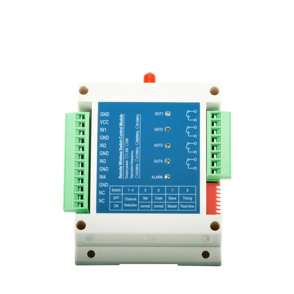
1. Overview
Y422-44-F transfers four digital input states to corresponding relay outputs over a wireless link. Each module has four switch inputs and four relay outputs. In real-time mode, modules can transfer signals in both directions. The module supports one master with five slaves; channel pairing also supports multiple masters with one slave. Confirm the channel mapping for a five-slave system before installation. In timing mode, signals go from the master inputs to the slave outputs.
2. Ordering Information
A basic link requires two compatible modules. Multi-module applications require compatible modules with individually paired channels. Specify the nominal 433, 470, 868 or 915 MHz version and matching antenna when ordering. Confirm the supplied configuration and accessories before installation.
Choose one frequency version for all modules in the link; confirm the applicable frequency and radio settings for the destination before ordering.
3. Key Features
- Four switch inputs and four relay outputs per module
- GFSK wireless modulation with 16 selectable channels
- Real-time and timing modes; channel pairing for one-to-many or many-to-one applications
- Wireless parameter configuration using a compatible configuration interface and PC software
4. Technical Specifications
| Parameter | Specification |
|---|---|
| Supply voltage | 9–30 V DC |
| Operating temperature | -40 to +85 °C |
| Digital inputs | 4 switch inputs, active when shorted to GND |
| Digital outputs | 4 relay contact outputs; one normally open contact pair per channel |
| Relay contact rating | Not specified; confirm voltage, current and load type before wiring |
| Modulation | GFSK |
| Frequency options | 433, 470, 868 or 915 MHz; specify when ordering |
| Antenna impedance | 50 Ω |
| RF output power | 1.5 W maximum; 31.5 dBm typical |
| Wireless channels | 16 selectable; default channel spacing 0.5 MHz, configurable |
| Receiver sensitivity | -121 dBm at the stated 2,400 air rate |
| Open-area range | Up to 4 km |
| Receive / transmit current | < 20 mA / < 300 mA, measured at 12 V and 25 °C |
| Standby current | < 5 mA at 12 V, timing mode, master not transmitting |
| Approximate dimensions | 90 × 115 × 40 mm; see mounting and connector clearances on the supplied unit |
| Weight | 150 g |
Range depends on antenna installation, obstructions and interference.
Mechanical Dimensions
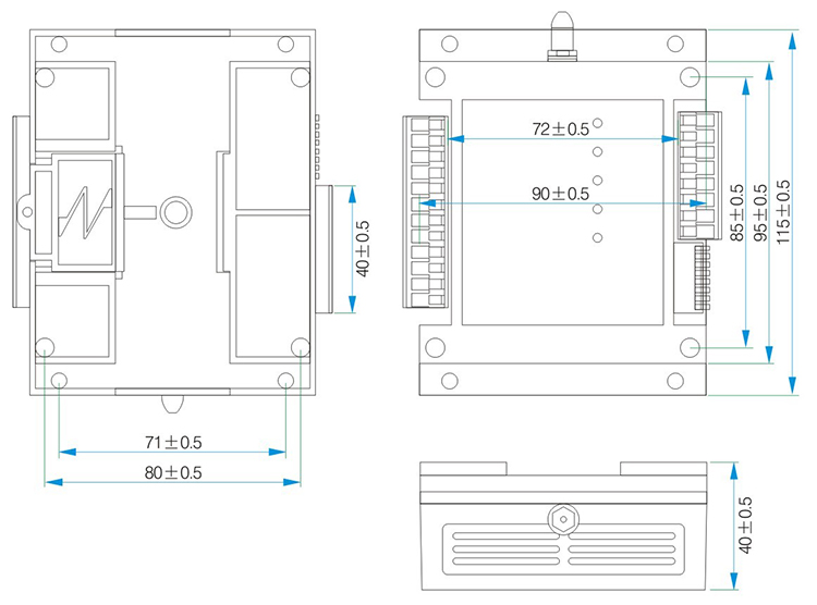
Dimensions are in millimeters. Allow additional space for the antenna and wiring; confirm mounting dimensions against the supplied unit.
5. Interfaces and Indicators
The module provides power terminals, four IN/GND input pairs, four two-terminal relay outputs, an antenna connector, output indicators, an alarm indicator and a DIP switch. Pins marked NC on the input side are reserved and must be left unconnected; they are not relay normally closed contacts.
6. Installation and Wiring
See the user manual for terminal assignments, mode selection and commissioning.
7. Important Notes
- Test output states and recovery with the actual configuration and loads isolated before use.
- Do not use the wireless link as the sole emergency-stop or personnel-safety path.
- Manufacturer: Hunan YenGear Tech Co., Ltd.
- Email: [email protected]
- Website: www.yengear.com