
Appearance
Y302-CC00 Power I/O Module Specification
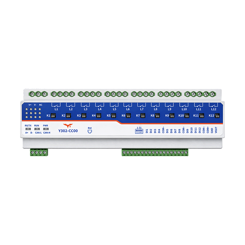
Contents
- Overview
- Ordering Information
- Key Features
- Technical Specifications
- Interfaces and Wiring
- Mechanical and Environmental
- Automation
1. Overview
The Y302-CC00 has 12 digital inputs and 12 latching relay outputs. It supports Modbus communication and supplier-documented intelligent control. The technical manual records the command-line Modbus integration boundary; verify the Work Mode value and rule persistence on the target firmware before deployment.
Configuration to verify: The supplier documentation lists both 12 and 8 relay outputs. Its product description and coil table indicate 12; confirm the supplied hardware before use.
2. Ordering Information
| Model | Digital inputs | Relay outputs | Analog inputs / outputs |
|---|---|---|---|
| Y302-CC00 | 12, NPN type | 12, latching | 0 / 0 |
The four model-code positions represent DI / DO / AI / AO; C represents 12 channels. Confirm the communication and control options when ordering. The supplier describes analog input and AC current sensing for other versions; these functions are not established for this model.
3. Key Features
- 12 latching relay outputs; supplier contact rating 50 A at 250 VAC
- 12 NPN-type digital inputs
- 12–30 VDC supply
- Modbus communication and intelligent control, including digital-input linkage, timing and relay interlocking
- Timed relay operation with automatic return
4. Technical Specifications
4.1 Supply and Environment
| Parameter | Specification |
|---|---|
| Supply voltage | 12–30 VDC |
| Supply current | Not specified |
| Operating temperature | −40 to +85 °C, as stated by supplier |
| Humidity / protection rating | Not specified |
4.2 Digital Inputs
| Parameter | Specification |
|---|---|
| Channels | 12 |
| Type | NPN |
| Input voltage, current, isolation and response time | Not specified; confirm before connection |
4.3 Relay Outputs
| Parameter | Specification |
|---|---|
| Channels | 12 latching relays; see configuration note above |
| Contact capacity | 50 A / 250 VAC, as stated by supplier |
| Endurance | 100,000 operations; test conditions unspecified |
| DC rating, load category, inrush and aggregate current | Not specified; confirm for the intended load |
| Contact configuration and power-loss state | Not specified; confirm for the supplied hardware |
The AC contact rating does not establish ratings for DC, motors, lamps, capacitive loads or total continuous current. Confirm the rating for the load, then select suitable wiring and protection.
4.4 Communication
| Parameter | Specification |
|---|---|
| Interfaces | Supplier lists RS485 and Ethernet, with 4G and Wi-Fi expansion; installed options require confirmation |
| Protocols | Supplier lists Modbus RTU, TCP and ASCII; interface-to-protocol mapping requires confirmation |
| Serial rates | 2400, 4800, 9600, 19200, 38400, 115200 bps |
| Default serial format | 9600 bps, 8 data bits, no parity, 1 stop bit |
| Default device address | 1, according to supplier instructions |
5. Interfaces and Wiring
The supplier identifies RS485 A+ and B− terminals and NPN digital inputs. Confirm the terminal numbering and load-side circuit topology against the supplied unit and its wiring diagram. Disconnect the supply and load circuits before wiring, and use appropriately rated conductors and protection. Do not assume the outputs are isolated dry contacts or that the module powers the load.
Connect multiple RS485 devices in a daisy chain and assign each a unique address. Confirm the reference, shielding, termination and isolation required for the installation.
6. Mechanical and Environmental
The supplier lists 180 × 88 × 64 mm and 773 g, but gives the same values for different channel counts. Before enclosure design, confirm the dimensions, weight, mounting arrangement and clearances for the supplied Y302-CC00.
7. Automation
The supplier documents digital-input linkage, output interlocks, schedules, scene control and up to 70 rules for the intelligent-control version. For command-line configuration, see the Technical Manual, which records the Modbus rule-block integration map and identifies the firmware-dependent values that still require validation.