
Appearance
Y302-4400 Power I/O Module Technical Manual
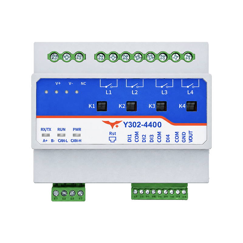
Contents
- Overview
- Default Settings
- Modbus Register Map
- Command Examples
- Configuration and Automation 5.1 Select Intelligent-Control Mode 5.2 Write a DI-to-DO Rule over Modbus 5.3 Verify the Command-Line Configuration
- Troubleshooting
1. Overview
This manual describes the supplier-documented Modbus functions for the Y302-4400, designated for 4 digital inputs and 4 latching relay outputs. The supplier’s terminal table also lists eight inputs for this four-input model. Confirm the terminals on the supplied unit.
An RTU request uses the format [address][function][data][CRC low][CRC high]. The examples use address 01, the stated default. Use the actual device address and recalculate the CRC. The examples are based on the supplier’s register descriptions and have not been tested on hardware.
2. Default Settings
| Parameter | Supplier-stated default |
|---|---|
| Device address | 1 |
| Baud rate | 9600 bps |
| Serial format | 8 data bits, no parity, 1 stop bit |
| Output state after power loss | Not specified; verify before connecting loads |
The supplier describes address 254 (FE) as a special address for communication with one device. It is not the standard Modbus broadcast address. Do not use it on a bus with multiple devices. Assign each device a unique address.
3. Modbus Register Map
The addresses below are zero-based protocol addresses. Client software may use 0xxxx / 1xxxx references or another numbering convention.
3.1 Relay Coils
| Channels | Protocol address | Functions |
|---|---|---|
| DO1–DO4 | 0x0000–0x0003 | 0x01 read, 0x05 write single, 0x0F write multiple |
For 0x05, write 0xFF00 to turn the relay on or 0x0000 to turn it off. Confirm the contact and load behavior on the supplied device. For 0x0F, use one bit per channel; channel 1 is the least significant bit of the first data byte.
3.2 Digital Inputs
| Channels | Protocol address | Function |
|---|---|---|
| DI1–DI4 | 0x0000–0x0003 | 0x02 read discrete inputs |
Confirm the physical inputs and active-state polarity on the supplied device.
3.3 Configuration Registers
| Holding register, decimal | Function | Supplier description |
|---|---|---|
1000 (0x03E8) | Baud rate | Source table; encoding requires confirmation |
1001 (0x03E9) | Backup | Source table; meaning and persistence require confirmation |
1002 (0x03EA) | Address offset | Device address configuration; permitted range and exact mapping require confirmation |
1003 (0x03EB) | Work mode | Source table; the numeric value for Intelligent Control is not published |
1004 (0x03EC) | Delay time | Source table; unit and persistence require confirmation |
The supplied documentation gives conflicting serial-parameter registers and address calculations. Treat the rows above as the source-table references, not a verified firmware contract. Verify the register numbers, baud-rate encoding, Work Mode value and any DIP-switch offset before use. The supplier states that serial setting changes require a restart; update the host settings to match.
4. Command Examples
The hexadecimal requests include the Modbus RTU CRC. They control real outputs. Disconnect the loads or make them safe before testing.
| Operation | Request |
|---|---|
| Read 4 relay states | 01 01 00 00 00 04 3D C9 |
| Read 4 digital inputs | 01 02 00 00 00 04 79 C9 |
| Turn relay 1 on | 01 05 00 00 FF 00 8C 3A |
| Turn relay 1 off | 01 05 00 00 00 00 CD CA |
A read response packs channel 1 into bit 0 of the first data byte and subsequent channels into increasing bit positions. The 4 channels occupy 1 byte. A successful single-coil write normally echoes the request; the response alone does not prove that the load switched.
5. Configuration and Automation
In normal mode, inputs and outputs operate independently. Intelligent-control mode links digital inputs to relay outputs and supports schedules, output interlocks, scene control and up to 70 rules. The command-line path below uses Modbus frames and does not require the supplier's GUI. The supplied Y302 manuals omit the Intelligent Control value and the persistent rule map, so the firmware-validation boundary in this section is mandatory.
5.1 Select Intelligent-Control Mode
The source table lists holding register 1003 (0x03EB) as Work Mode, but it does not publish the numeric value for Intelligent Control. Read this register with function 0x03 first. Do not write a guessed value. Confirm the value against the exact firmware or a controlled hardware test; a mode change may require a restart.
5.2 Write a DI-to-DO Rule over Modbus
The register layout below was reconstructed from the supplier's current DLC package because the Y302 manuals do not publish it. It is an integration aid, not a manufacturer-published guarantee. Rule n is zero-based and starts at holding register 14000 + 7n; write one rule with function 0x10 (write multiple holding registers).
| Byte offset | Field | Encoding |
|---|---|---|
| 0 | Reserved | 0x00 |
| 1 | Rule header | Bits 7–5: trigger type (1 = DI); bit 4: event mode (0 = event trigger, 1 = event force); bits 3–0: action (1 = close relay, 2 = open relay, 3 = invert) |
| 2 | DI condition | Bits 7–5: state (0 = high/conducting, 1 = low/disconnected); bits 4–0: zero-based DI index |
| 3 | Reserved | 0x00 |
| 4–5 | Exit condition | Big-endian uint16; supplier package UI uses 0.01 s units |
| 6–7 | Stable condition | Big-endian uint16; supplier package UI uses 0.01 s units |
| 8–9 | Action time | Big-endian uint16; supplier package UI uses 0.1 s units |
| 10–13 | DO selection | Four-byte bit mask; bit 0 of byte 10 is DO1, bit 1 is DO2, and so on |
For example, rule 0 for DI1 high/conducting → DO1 open, event-triggered, with zero delays, has this 14-byte payload:
text
00 22 00 00 00 00 00 00 00 00 01 00 00 00As seven big-endian holding-register values, the payload is:
text
0022 0000 0000 0000 0000 0100 0000For unit address 01, register 14000 (0x36B0), the corresponding RTU write is:
text
01 10 36 B0 00 07 0E 00 00 22 00 00 00 00 00 00 00 01 00 00 00 9D 80Read the same seven registers back with:
text
01 03 36 B0 00 07 0A 67The frame is an untested integration example. Validate the returned data, trigger the input with the load isolated, and confirm the relay state before connecting a load.
5.3 Verify the Command-Line Configuration
- Read the rule block with function
0x03, then read the inputs with function0x02and the outputs with function0x01during a controlled test. - The direct relay commands in Command Examples change the current DO state; they do not create or modify persistent linkage rules.
- Y302 models have no AI channels, so use DI-to-DO rules. Do not send AI rule blocks to these SKUs.
- The supplied manuals do not publish the Work Mode enum, save/apply semantics or rule-register contract. The map above is reverse-engineered from the current supplier package and has not been validated on Y302 hardware. Stop integration if the target firmware rejects register 14000 or returns a different layout.
The supplier also describes timed close and timed open commands in 0.1 s units. Its examples and field descriptions conflict. Verify command addresses, action codes and persistence on the device before use. The supplier states that the software-selected timed mode is not saved to the device and that individual timed commands do not change other channels.
6. Troubleshooting
- No communication: check the DC supply, installed interface, RS485 polarity, serial format and device address. Check the network one device at a time.
- No relay action: check the returned frame, channel and command. Isolate the supply before checking terminal wiring and load protection.
- Unexpected local operation: inspect any configured automation rules and the selected operating mode before reconnecting a load.
- Multiple devices: assign unique addresses and avoid the supplier's special address
254on a shared bus.